Engine starting system and method

Inactive Publication Date: 2009-03-05
HONDA MOTOR CO LTD
View PDF4 Cites 4 Cited by
  • Summary
  • Abstract
  • Description
  • Claims
  • Application Information

AI Technical Summary

Benefits of technology

[0016]According to the first aspect of the present invention, the engine starting system includes the notifying unit for notifying the length of the recoil rope required to turn the crankshaft from the turning position of the crankshaft encountered when the piston is located in the vicinity of the compression stroke top dead center to a turning position of the crankshaft adapted to start pulling the recoil rope in order to initiate start operation of the 4-stroke engine. Thus, before the start operation of the engine, the crankshaft is previously turned to the turning position encountered when the piston is located at the compression stroke top dead center and the recoil rope is operatively pulled to a position corresponding to such a length. This can turn the crankshaft to the start operation initiating position suitable to initiate the start operation for the engine. If the recoil rope is pulled from the start operation initiating position to execute the start operation for the engine, the crankshaft can be turned from the uniform position satisfactory for starting performance, whereby the engine can be started easily and stably.
[0017]According to the second aspect of the present invention, the notifying unit is the mark provided on the recoil rope at a position required to turn the crankshaft from a near-tip of the recoil rope in order to displace the piston from the vicinity of the compression stroke top dead center to the vicinity of the next exhaust stroke top dead stroke. Thus, electric power generation by the generator, the supply of the fuel, and the ignition by the ignition device can sequentially be performed to reduce the variations of the start executed by the recoil starter, facilitating the start of the engine. In addition, the engine starting system can be provided that can provide satisfa

Problems solved by technology

However, the time when start operation is initiated, i.e., a crankshaft rotational position encountered when the recoil rope is started to be pulle

Method used


Image

  • Engine starting system and method
  • Engine starting system and method
  • Engine starting system and method

Examples


Example

[0031]It should be understood that only structures considered necessary for illustrating selected embodiments of the present invention are described herein. Other conventional structures, and those of ancillary and auxiliary components of the system, will be known and understood by those skilled in the art.

[0032]An illustrative embodiment of an engine starting system according to the present invention is described in detail with reference to the drawings.

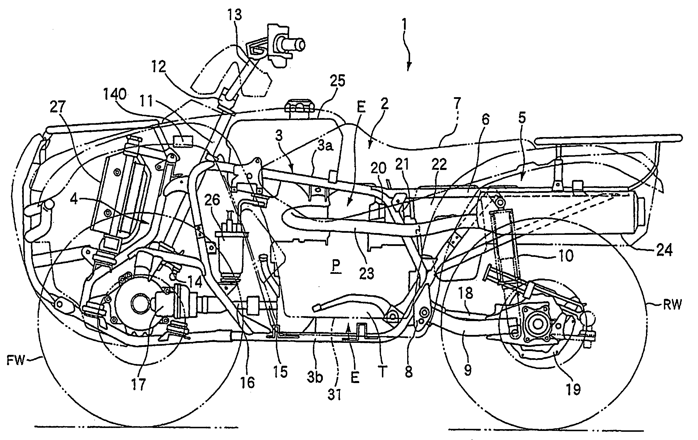
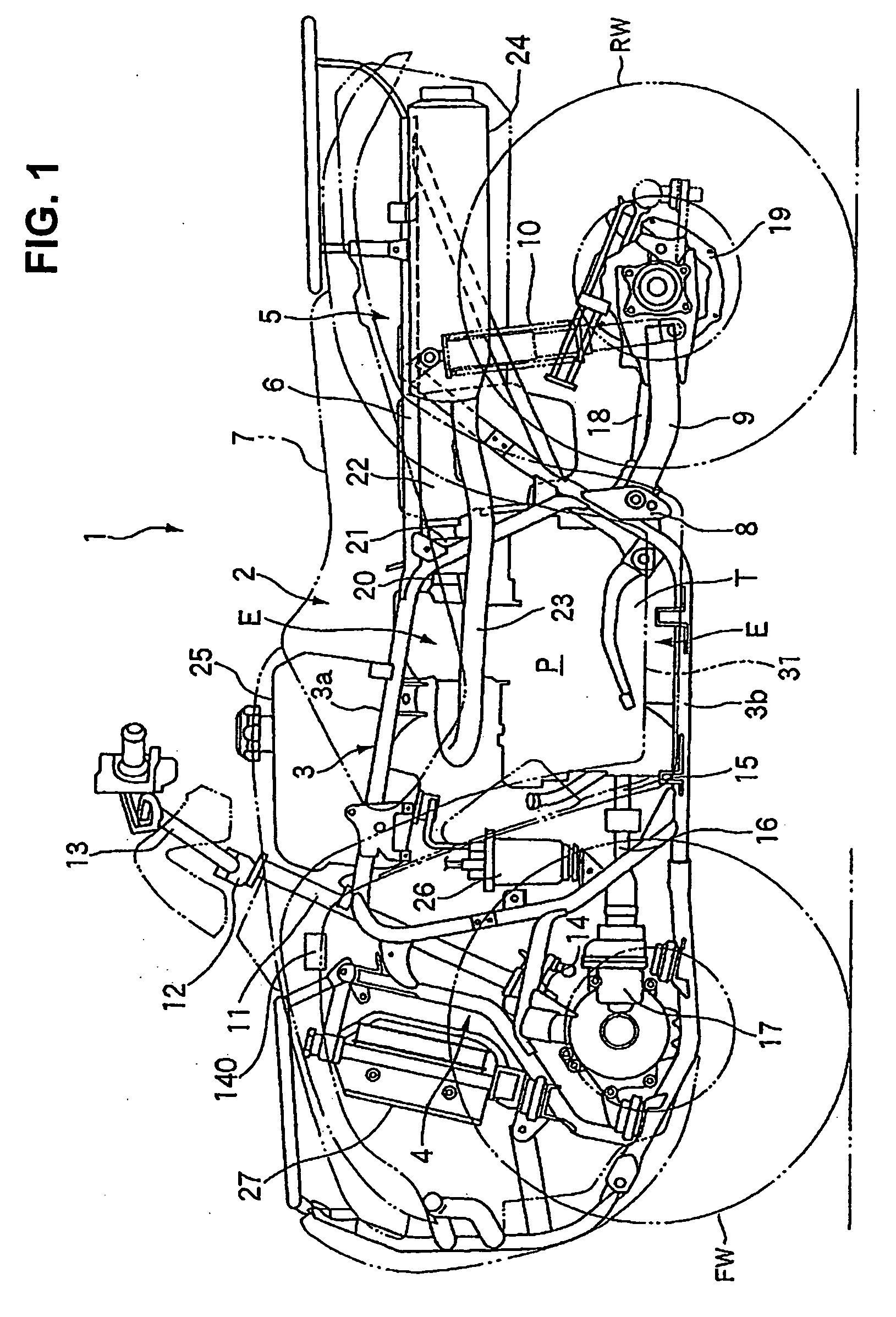
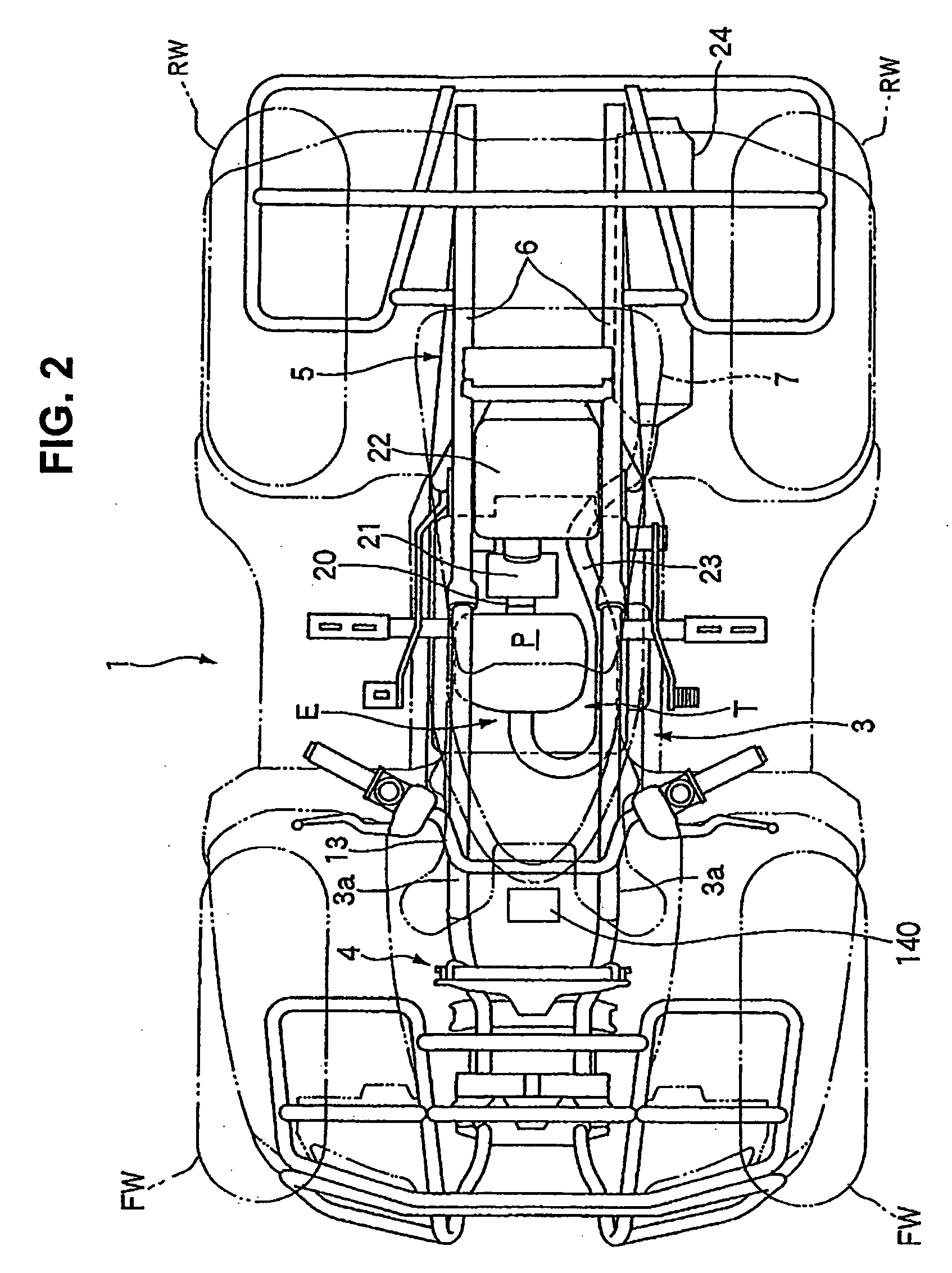
[0033]FIG. 1 is a side view of an all terrain vehicle (ATV) 1 having a water-cooled engine E (with a body cover and the like removed for clarity) mounted thereon with according to the embodiment. FIG. 2 is a top plan view of the ATV 1 of FIG. 1. It should be noted that the front, rear or back, left and right direction referred in the disclosure of the present invention are determined based on a normal vehicle advancing direction.

[0034]Referring to FIGS. 1 and 2, the all terrain vehicle 1 is a saddle-ride type four-wheeled vehicle in...


PUM


Abstract

An engine starting system includes a recoil starter with a recoil rope having a mark formed thereon, defining a predetermined length of the recoil rope required to turn a crankshaft from a compression stroke top dead center position to a start-operation-initiating position suitable to start operation of a 4-stroke engine. A method of starting a 4-stroke engine includes steps of pulling the recoil rope to turn a crankshaft to an initial position where a piston is located near a compression stroke top dead center; pulling the recoil rope again to the position of the mark on the rope, to rotate the crankshaft from the initial position to a start-operation-initiating position; and pulling the recoil rope once again to further turn the crankshaft from the start-operation-initiating position suitable for starting the engine.

Description

CROSS-REFERENCE TO RELATED APPLICATIONS[0001]The present application claims priority under 35 USC §119 based on Japanese patent application No. 2007-221155, filed on Aug. 28, 2007. The entire subject matter of this priority document is incorporated by reference herein.BACKGROUND OF THE INVENTION[0002]1. Field of the Invention[0003]The present invention relates to an engine starting system and method. More particularly, the present invention relates to an engine starting system and method for starting a 4-stroke engine using a recoil starter.[0004]2. Description of the Background Art[0005]It is known that some engines mounted on buggy vehicles, all-terrain vehicles or the like, or some engines for agricultural implements are provided with a recoil starter, and such engines are started by pulling a recoil rope, which is generally performed by a user.[0006]An example of such known engine provided with a recoil starter is disclosed in Japanese Laid-Open Patent No. 2005-155375.[0007]Acco...

Claims


Application Information

Patent Timeline
IPC IPC(8): F02N3/02
CPCF02N3/02F02P1/00F02N19/005
Inventor YAMAZAKI, MASAKI
Owner HONDA MOTOR CO LTD
Why Eureka
Try Eureka