Oil lubricated swashplate

a technology of oil lubrication and swashplate, which is applied in the direction of bearing cooling, machines/engines, transportation and packaging, etc., can solve the problems of stalling of the retreating blade, limited lift equalization due to flapping, and much more limited maximum flight speed of fixed wing aircra

Active Publication Date: 2016-02-16
SKYWORKS GLOBAL INC
View PDF28 Cites 15 Cited by
  • Summary
  • Abstract
  • Description
  • Claims
  • Application Information

AI Technical Summary

Benefits of technology

[0027]In another aspect of the invention, a method for operating a rotary wing aircraft includes receiving oil from a return oil line and pumping oil to a feed line, where the feed oil line and return oil line are in fluid communication with a bearing interposed between a rotating ring an

Problems solved by technology

Although rotating wing aircraft provide the significant advantage of vertical takeoff and landing (VTOL), they are much more limited in their maximum flight speed than are fixed wing aircraft.
However, lift equalization due to flapping is limited by a phenomenon known as “retreating blade stall.” As noted above, flapping of the rotor blades increases the angle of attack of the retreating blade.
However, at certain higher speeds, the increase in the blade angle of attack required to equalize lift on the advancing and retreating blades

Method used


Image

  • Oil lubricated swashplate
  • Oil lubricated swashplate
  • Oil lubricated swashplate

Examples


Embodiment Construction

[0062]It will be readily understood that the components of the present invention, as generally described and illustrated in the drawings herein, could be arranged and designed in a wide variety of different configurations. Thus, the following more detailed description of the embodiments of the system and method of the present invention, as represented in the drawings, is not intended to limit the scope of the invention, as claimed, but is merely representative of various embodiments of the invention. The illustrated embodiments of the invention will be best understood by reference to the drawings, wherein like parts are designated by like numerals throughout.

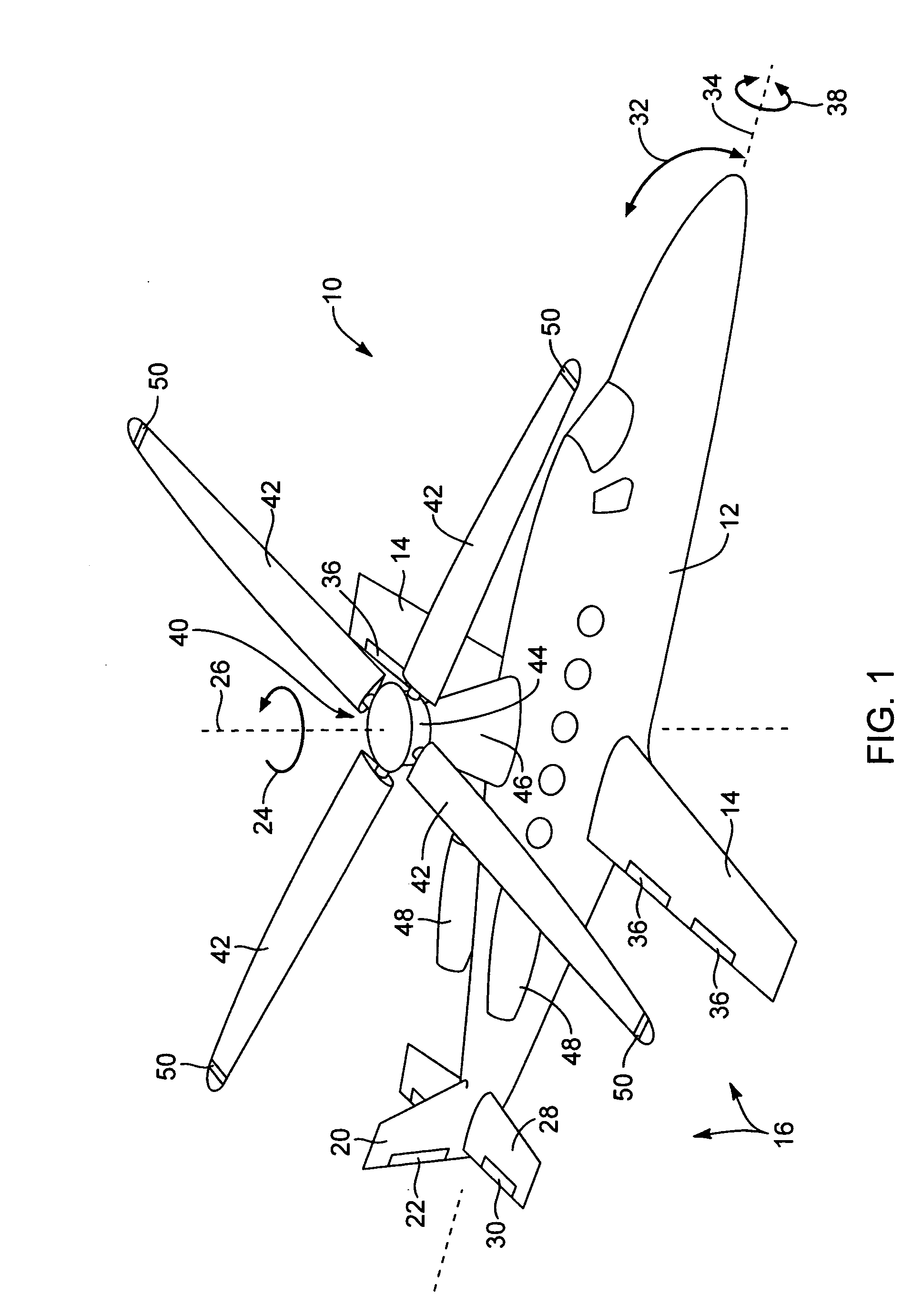
[0063]Referring to FIG. 1, an aircraft 10 includes a fuselage 12 defining a cabin for carrying an operator, passengers, cargo, or the like. The fuselage 12 may include one or more fixed wings 14 shaped as airfoils for providing lift to the aircraft. The wings 14 may be configured such that they provide sufficient lift to overcom...


PUM


Abstract

A rotor system for a reactive drive rotary wing maintains the rigidity of the rotor and eliminates play between flight controls and the rotor by mounting swashplate actuators to a flange rigidly secured to the mast. Apparatus and methods perform thermal management of the rotor in order to avoid bearing failure or loss of bearing preload. Methods include modulating the temperature of oil pumped over one or more of the mast bearing, swashplate bearing, and spindle bearing. The temperature of air passively or actively drawn through rotor may also be modulated to maintain bearing temperature within a predetermined range. The rotor includes structures for reducing pressure losses and drag on components due to air flow through the rotor. A rotor facilitates thermal management by oil and air flow.

Description

RELATED APPLICATIONS[0001]This application claims the benefit of U.S. Provisional Patent Application Ser. No. 61 / 403,099, filed on Sep. 9, 2010, U.S. Provisional Patent Application Ser. No. 61 / 403,097, filed on Sep. 9, 2010, U.S. Provisional Patent Application Ser. No. 61 / 381,313, filed on Sep. 9, 2010, U.S. Provisional Patent Application Ser. No. 61 / 403,111, filed on Sep. 9, 2010, U.S. Provisional Patent Application Ser. No. 61 / 403,081, filed on Sep. 9, 2010, U.S. Provisional Patent Application Ser. No. 61 / 403,135, filed on Sep. 9, 2010, U.S. Provisional Patent Application Ser. No. 61 / 466,177, filed on Mar. 22, 2011, U.S. Provisional Patent Application Ser. No. 61 / 403,113, filed on Sep. 9, 2010, U.S. Provisional Patent Application Ser. No. 61 / 409,478, filed on Nov. 2, 2010, U.S. Provisional Patent Application Ser. No. 61 / 409,470, filed on Nov. 2, 2010, U.S. Provisional Patent Application Ser. No. 61 / 517,413, filed on Apr. 19, 2011, U.S. Provisional Patent Application Ser. No. 61 / 46...

Claims


Application Information

Patent Timeline
IPC IPC(8): B64C27/605F01M5/00F16C33/66B64C27/18
CPCB64C27/605F16C33/667B64C27/18F01M5/005F16C2229/00B64C27/025B64C27/26F16C19/525F16C37/007F16C2326/43
Inventor VAN, DER, WESTHUIZEN, JACOB, JOHANNES
Owner SKYWORKS GLOBAL INC
Why Eureka
Try Eureka