
Camera and image processing method for spectroscopic analysis of captured image

a spectroscopic analysis and image technology, applied in the field of cameras and image processing methods, can solve the problems of large error, abnormal brightness of parts of a spectroscopic image, short distance between the light source and the imaging lens, etc., and achieve the effect of high-precision imag

Active Publication Date: 2016-02-23
SEIKO EPSON CORP
View PDF12 Cites 5 Cited by
  • Summary
  • Abstract
  • Description
  • Claims
  • Application Information

AI Technical Summary

Benefits of technology

[0007]An advantage of some aspects of the invention is to provide a camera capable of acquiring a high-precision image even when light from a light source is specularly reflected off the surface of an object being imaged and also provide an image processing method.
[0025]In this configuration, for example, when a predetermined distance set based on user's operation is used, the user can check an image and then set an area (predetermined distance described above) in which a small number of abnormal pixels are present. Further, when such an area is automatically set in accordance with the number of normal pixels around an abnormal pixel, and the number of abnormal pixels is large, increasing the predetermined distance allows an area for calculating the light amount correction value to be so set that a large number of normal pixels are present in the area, whereby the amount of light at the abnormal pixel can precisely be corrected to a normal amount of light. Further, in this case, when the number of abnormal pixels is small, reducing the predetermined distance allows the light amount correction value to be calculated based on normal pixels closer to the detected abnormal pixel, whereby a precise light amount correction value can be calculated.
[0028]In the aspect of the invention with the configuration described above, since the wavelength of light to be separated by the spectroscopic device can be changed, spectroscopic images corresponding to a plurality of wavelengths can be acquired. Replacing the amount of light at an abnormal pixel corresponding to a specular reflection portion in each of the spectroscopic images allows acquisition of a high-precision spectroscopic image at each of the wavelengths.
[0030]In the aspect of the invention with the configuration described above, the spectroscopic device is a wavelength tunable Fabry-Perot etalon. A wavelength tunable Fabry-Perot etalon has a simple configuration in which a pair of reflection films are simply so disposed that they face each other and can readily change the wavelength of light to be separated by changing the dimension of the gap between the reflection films. Using a thus configured wavelength tunable Fabry-Perot etalon allows reduction in the size and thickness of the spectroscopic camera as compared with a case where an AOTF (acousto-optic tunable filter), an LCTF (liquid crystal tunable filter), or any other large spectroscopic device is used.

Problems solved by technology

However, providing such a light source in the spectroscopic camera, which is compact as described above, results in a short distance between the light source and an imaging lens.
In this case, light specularly reflected off the surface of an object being imaged enters the imaging lens, undesirably resulting in abnormal brightness of part of a spectroscopic image.
When the amounts of light at the pixels in the image vary from each other, for example, when an edge portion is present in a pixel area, using the average as the light amount correction value possibly results in a large error.

Method used


Image

  • Camera and image processing method for spectroscopic analysis of captured image
  • Camera and image processing method for spectroscopic analysis of captured image
  • Camera and image processing method for spectroscopic analysis of captured image

Examples


first embodiment

[0047]A spectroscopic analysis apparatus (camera) of a first embodiment according to the invention will be described below with reference to the drawings.

Schematic Configuration of Spectroscopic Analysis Apparatus

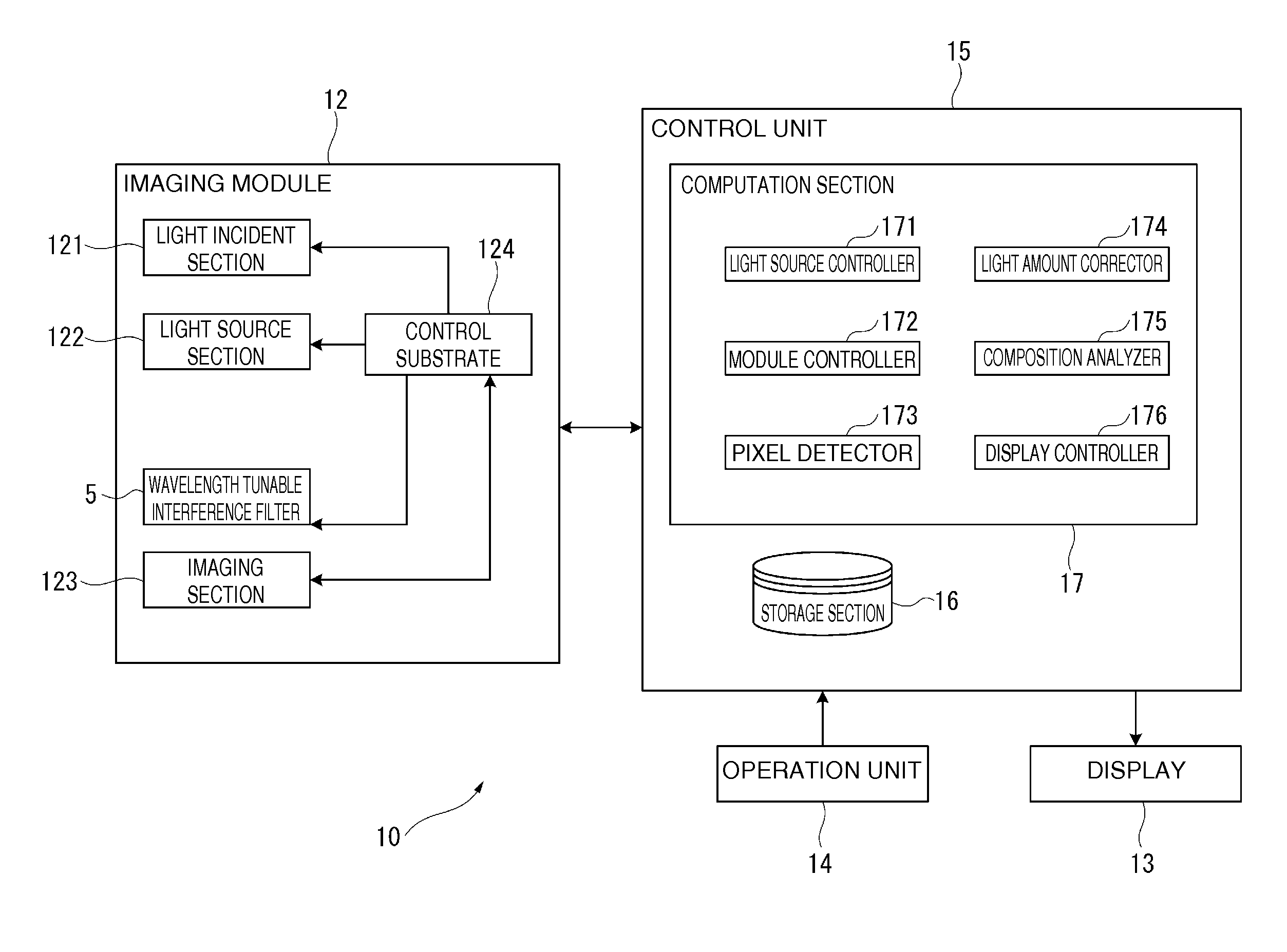
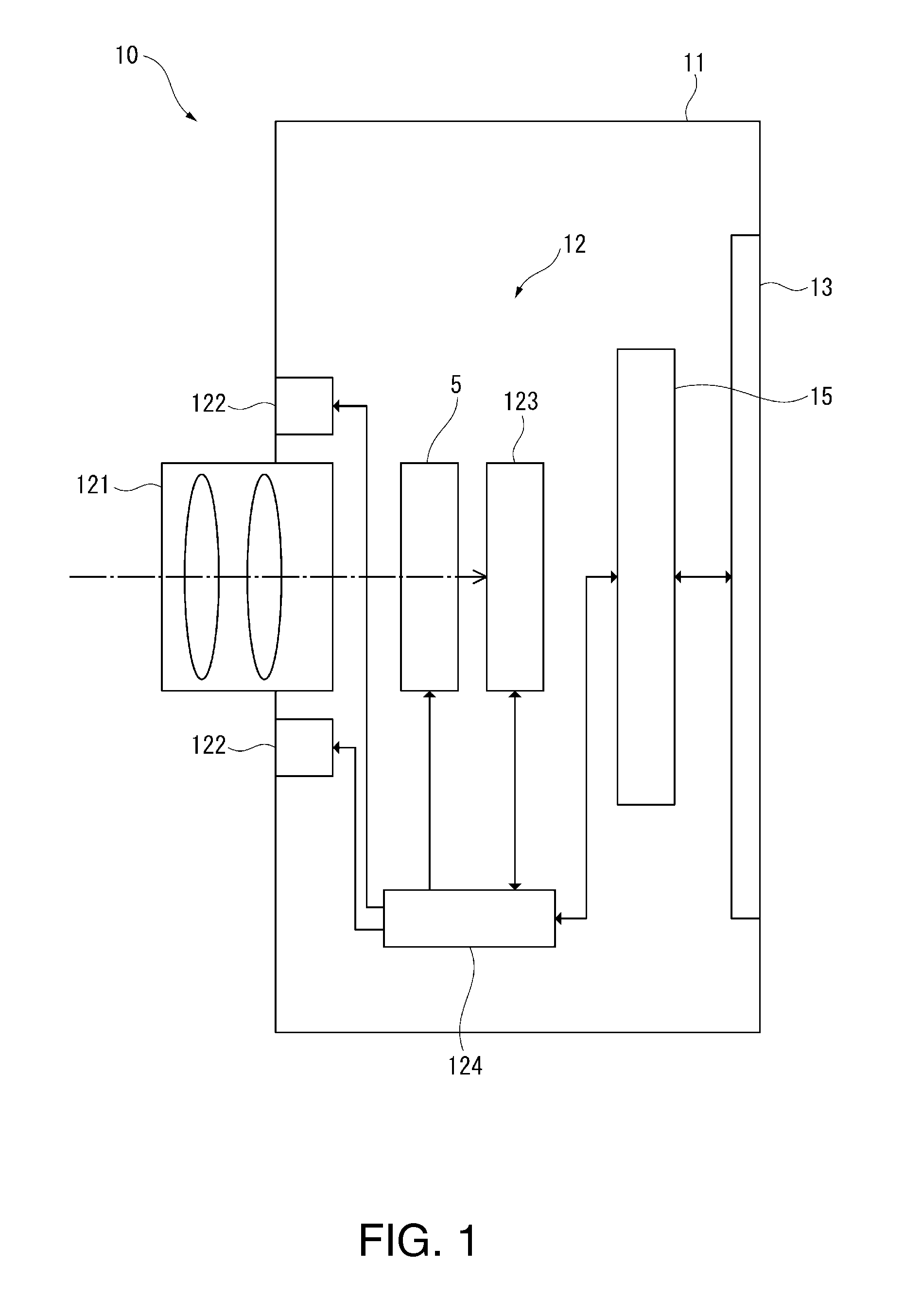
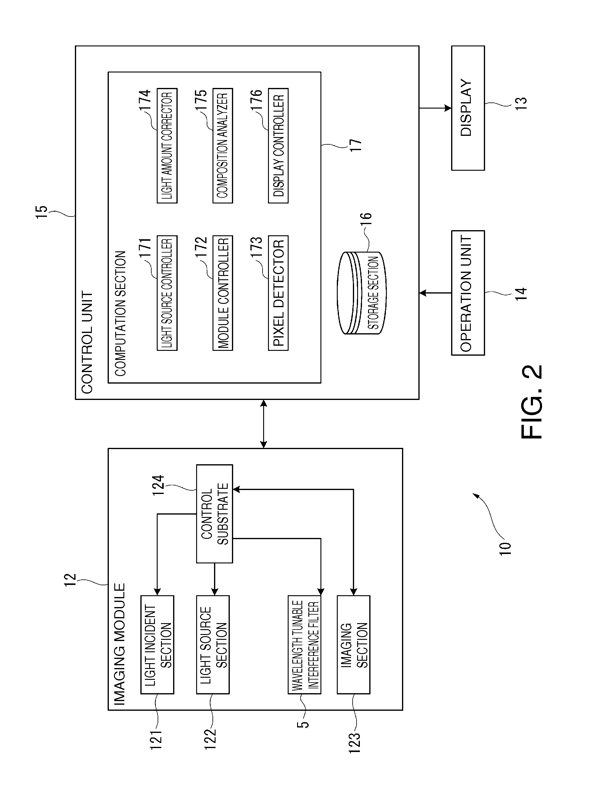
[0048]FIG. 1 is a schematic view showing a schematic configuration of the spectroscopic analysis apparatus of the first embodiment. FIG. 2 is a block diagram showing the schematic configuration of the spectroscopic analysis apparatus.

[0049]A spectroscopic analysis apparatus 10 is a camera according to an embodiment of the invention and an apparatus that captures spectroscopic images of an object being imaged at a plurality of wavelengths, analyzes a spectrum in an infrared wavelength region (target wavelength region in spectroscopic image) at each pixel based on the captured spectroscopic images, and analyzes the composition of the object being imaged based on the analyzed spectra.

[0050]The spectroscopic analysis apparatus 10 of the present embodiment includes an enclosure ...

second embodiment

[0145]A second embodiment according to the invention will next be described with reference to the drawings.

[0146]In the first embodiment described above, the amount of light at an abnormal pixel (i, j) in a spectroscopic image Pλk is replaced, by way of example, with a light amount correction value in the form of the average of the amounts of light at normal pixels in a predetermined pixel area including the abnormal pixel. The second embodiment differs from the first embodiment described above in that the light amount correction value is calculated in the form of the median of the amounts of light at normal pixels.

[0147]FIG. 10 is a flowchart showing the light amount correction process in the second embodiment.

[0148]In the following description, the same configurations as those in the first embodiment and the items having already been described in the first embodiment have the same reference characters and will not be described or described in a simplified manner.

[0149]In the prese...

third embodiment

[0160]A third embodiment according to the invention will next be described with reference to the drawings.

[0161]In the first and second embodiments described above, the average or median of the amounts of light at normal pixels is selected as the light amount correction value in step S100. The present embodiment differs from the first and second embodiments described above in that the average of the amounts of light at normal pixels in the quartile range is acquired.

[0162]FIG. 11 is a flowchart showing the light amount correction process in the third embodiment.

[0163]In the present embodiment, the light amount corrector 174 carries out the processes in steps S101 to S114 as in the second embodiment to sort the light amount sequence d_n(0) to d_n(c−1), which represent the amounts of light at normal pixels in a pixel area, to acquire a sorted sequence S_n(1) to S_n(c), as shown in FIG. 11.

[0164]Thereafter, in the present embodiment, the light amount corrector 174 calculates the light ...


PUM


Abstract

A spectroscopic analysis apparatus includes a light source section that radiates light toward an object being imaged, an imaging section that captures light reflected off the object being imaged to acquire an image, a pixel detector that detects an abnormal pixel in the image which is a pixel where a reflectance ratio is greater than or equal to 1 and detects normal pixels in the image each of which is a pixel where the reflectance ratio is smaller than 1, and a light amount corrector that calculates a light amount correction value based on the amounts of light at normal pixels in a pixel area including the abnormal pixel in the image and replaces the amount of light at the abnormal pixel with the light amount correction value.

Description

BACKGROUND[0001]1. Technical Field[0002]The present invention relates to a camera and an image processing method.[0003]2. Related Art[0004]There is a known apparatus of related art that radiates light toward an object being imaged and captures light reflected off the object being imaged to produce a captured image (see JP-A-2009-33222, for example).[0005]The imaging apparatus (spectroscopic camera) described in JP-A-2009-33222 causes light from the object to be incident on a Fabry-Perot interference filter and allows an image sensor to receive light having passed through the Fabry-Perot interference filter for acquisition of a spectroscopic image.[0006]A spectroscopic camera using a Fabry-Perot interference filter has an advantage of being compact and lightweight, as described in JP-A-2009-33222. On the other hand, to acquire a spectroscopic image based on a sufficient amount of near infrared light, a near infrared light source needs to be provided in an imaging apparatus body. Howe...

Claims


Application Information

Patent Timeline
Patent Type & Authority Patents(United States)
IPC IPC(8): H04N5/243H04N5/217G01J3/26G01J3/28
CPCH04N5/243G01J3/26G01J3/28G01J3/2823H04N5/2176H04N25/63H04N23/76
Inventor FUNAMOTO, TATSUAKI
Owner SEIKO EPSON CORP
Learn More