Diffracted Wave Imaging Method, Device and Electronic Apparatus

Active Publication Date: 2022-06-23
CHINA UNIV OF MINING & TECH (BEIJING)
View PDF3 Cites 0 Cited by
  • Summary
  • Abstract
  • Description
  • Claims
  • Application Information

AI Technical Summary

Benefits of technology

The present patent provides a method for high-precision imaging of diffracted waves in a to-be-processed area. The method involves acquiring pre-stack seismic wave field data, extracting target data of a target imaging point, fitting target time sample points, and determining migration imaging data of the target imaging point. By using different manifestations of the reflected wave and the diffracted wave in the target data and through Gaussian model fitting, the Fresnel zone distribution of the reflected wave is accurately positioned and then the stationary point position signal of the reflected wave is accurately separated from the target data, so that the diffracted wave is separated, realizing a high-precision imaging of the diffracted wave. The technical effect is that the diffracted wave imaging method has a high precision in imaging diffracted waves.

Problems solved by technology

However, compared to the reflected waves, the diffracted waves are characterized by more rapid amplitude attenuation and have much weaker energy during the propagation process, and are easily masked by the reflected waves with strong energy.
In the existing diffracted wave imaging methods, the diffracted wave is mostly separated in the common-offset domain or the post-stack domain, using only the difference in kinematic characteristics of the reflected wave and the diffracted wave, which does not facilitate the diffracted wave imaging.
In addition, it is difficult to effectively estimate the Fresnel zone by the Fresnel zone estimation based diffracted wave common-imaging-point gather imaging method, having a larger error.
In summary, the diffracted wave imaging method in the prior art has the technical problem of a poor precision in imaging a diffracted wave.

Method used


Image

  • Diffracted Wave Imaging Method, Device and Electronic Apparatus
  • Diffracted Wave Imaging Method, Device and Electronic Apparatus

Examples


embodiment 1

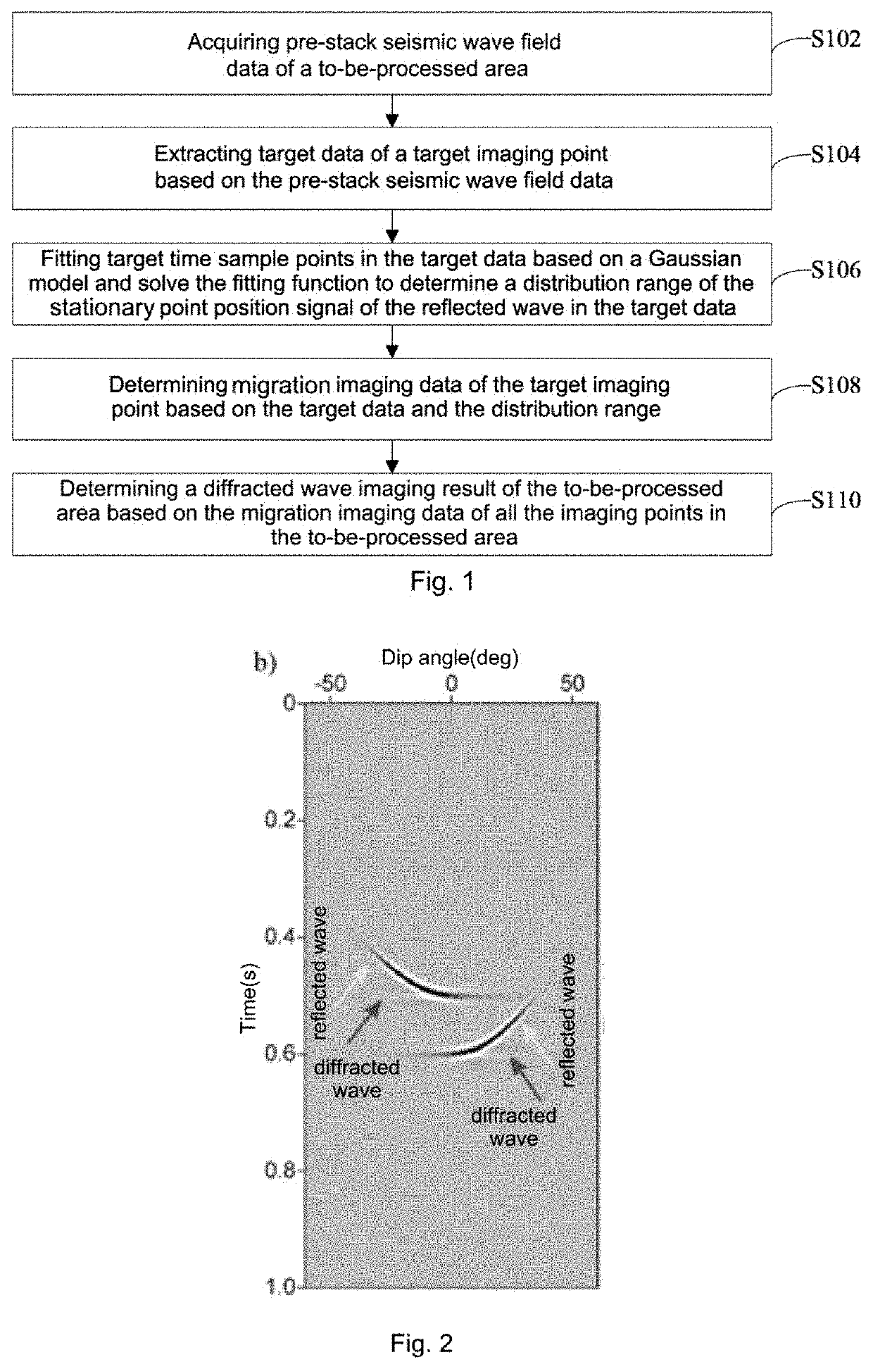
[0028]FIG. 1 is a flowchart of a diffracted wave imaging method provided by an embodiment of the present disclosure. As shown in FIG. 1, the method specifically comprises the following steps:

[0029]Step S102. Acquire pre-stack seismic wave field data of a to-be-processed area.

[0030]Step S104. Extract target data of a target imaging point based on the pre-stack seismic wave field data.

[0031]In the case of conducting geological exploration in the to-be-processed area in the field, a seismic source may occur by dropping explosive packs or using a seismic source instrument, so that the pre-stack seismic wave field data of the to-be-processed area is obtained, where the above pre-stack seismic wave field data may be obtained by a seismic exploration instrument.

[0032]After the pre-stack seismic wave field data is obtained, the target data of the target imaging point is firstly extracted, wherein the target imaging point is any imaging point of all the imaging points in the to-be-processed ...

embodiment 2

[0071]The embodiment of the present disclosure also provides a diffracted wave imaging device. The diffracted wave imaging device is mainly configured to execute the diffracted wave imaging method provided in Embodiment 1. The diffracted wave imaging device provided by the embodiment of the present disclosure is introduced below specifically.

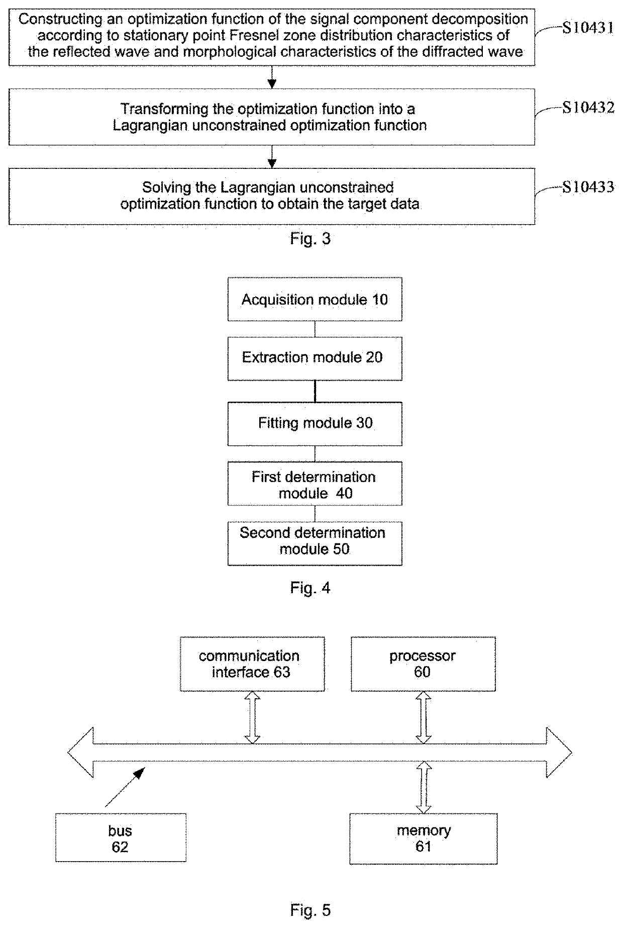
[0072]FIG. 4 is a function module diagram of a diffracted wave imaging device provided by an embodiment of the present disclosure. As shown in FIG. 4, the device mainly comprises: an acquisition module 10, an extraction module 20, a fitting module 30, a first determination module 40, and a second determination module 50, where:

[0073]the acquisition module 10 is configured to acquire pre-stack seismic wave field data of a to-be-processed area.

[0074]The extraction module 20 is configured to extract the target data of the target imaging point based on the pre-stack seismic wave field data, wherein the target imaging point is any imaging point of al...

embodiment 3

[0095]Referring to FIG. 5, an embodiment of the present disclosure provides an electronic apparatus comprising a processor 60, a memory 61, a bus 62 and a communication interface 63, where the processor 60, the communication interface 63 and the memory 61 are connected through the bus 62; and the processor 60 is configured to execute executable module(s) stored in the memory 61, such as computer program(s).

[0096]In the above, the memory 61 may comprise a high-speed random access memory (RAM), and may also comprise a non-volatile memory, for example, at least one disk memory. A communication connection between the network element of the system and at least one other network element is implemented through at least one communication interface 63 (which may be wired or wireless), and the Internet, a wide area network, a local network, a metropolitan area network, etc. may be used.

[0097]The bus 62 may be an ISA bus, a PCI bus, an EISA bus, or the like. The bus may be classified into an a...


PUM


Abstract

The present disclosure provides a diffracted wave imaging method, device and electronic apparatus. The method comprises: acquiring pre-stack seismic wave field data of a to-be-processed area; extracting target data of a target imaging point; fitting target time sample points in the target data based on the Gaussian model and solving the fitting function to determine a distribution range of the stationary point position signal of the reflected wave in the target data; determining migration imaging data of the target imaging point based on the target data and the distribution range; and determining a diffracted wave imaging result of the to-be-processed area based on the migration imaging data of all the imaging points in the to-be-processed area.

Description

CROSS-REFERENCE TO RELATED APPLICATIONS[0001]The present disclosure claims priority to Chinese Patent Application No. 202010846038.6, filed with the Chinese Patent Office on Aug. 20, 2020, entitled “Diffracted Wave Imaging Method, Device and Electronic Apparatus”, the contents of which are incorporated herein by reference in its entirety.TECHNICAL FIELD[0002]The present disclosure relates to the technical field of seismic explorations, in particular to a diffracted wave imaging method, device and electronic apparatus.BACKGROUND ART[0003]Small-scale, non-continuous geological bodies, such as faults, collapse columns and cracks, are often closely related to distributions of mineral resources. Precisely positioning the inhomogeneous and discontinuous geological bodies may effectively improve the success rate of exploration, reduce costs, and avoid possible occurrences of geological disasters and avoid risks. A diffracted wave is a seismic response to small-scale geological bodies and c...

Claims


Application Information

Patent Timeline
IPC IPC(8): G01V1/34G01V1/30
CPCG01V1/345G01V2210/60G01V1/303G01V1/306G01V2210/62G01V1/301
Inventor LIN, PENGZHAO, JINGTAOPENG, SUPINGCUI, XIAOQIN
Owner CHINA UNIV OF MINING & TECH (BEIJING)
Why Eureka
Try Eureka