Eureka AIR delivers breakthrough ideas for toughest innovation challenges, trusted by R&D personnel around the world.

Portable stamp

Active Publication Date: 2016-03-01
SUN SAME ENTERPRISES
View PDF9 Cites 2 Cited by
  • Summary
  • Abstract
  • Description
  • Claims
  • Application Information

AI Technical Summary

Benefits of technology

The present invention provides a portable stamp with a stamp housing, a driving member, an operating member, an ink member, and a stamp seat. The invention allows the ink member and stamp seat to pivot out of the stamp housing or be folded in the stamp housing. The invention also ensures that the ink member can be folded at a specific position in the stamp housing and that the stamping surface of the stamp pad is sure to touch the ink pad of the ink member and be coated with the ink uniformly. The technical effects of the invention are improved convenience, portability, and consistent and uniform ink coating.

Problems solved by technology

Moreover, after the conventional portable stamp is used for some time, the ink pad may become thin due to pressing, and the stamp pad may also become thin due to wearing down.

Method used


Image

  • Portable stamp
  • Portable stamp
  • Portable stamp

Examples


Embodiment Construction

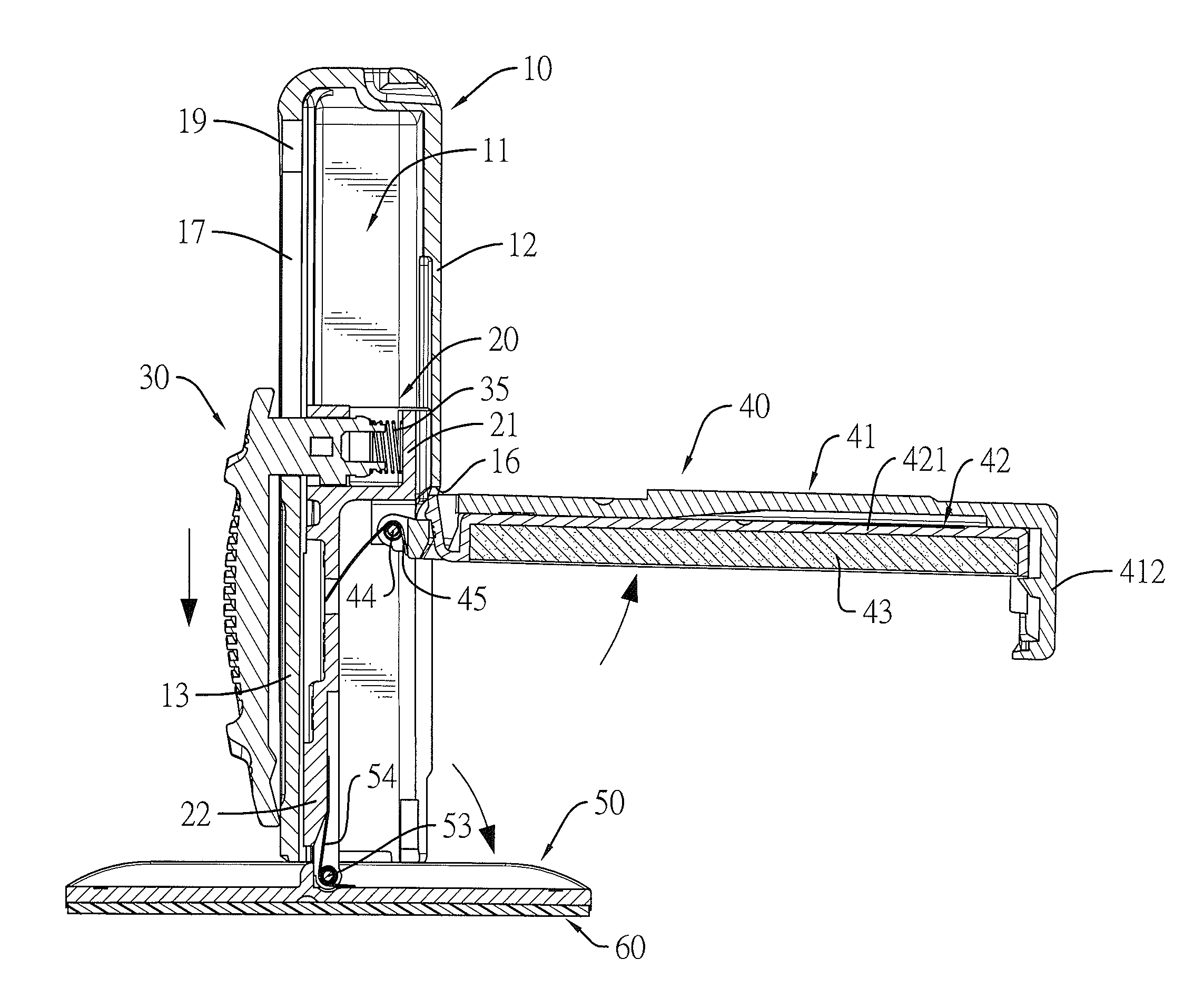
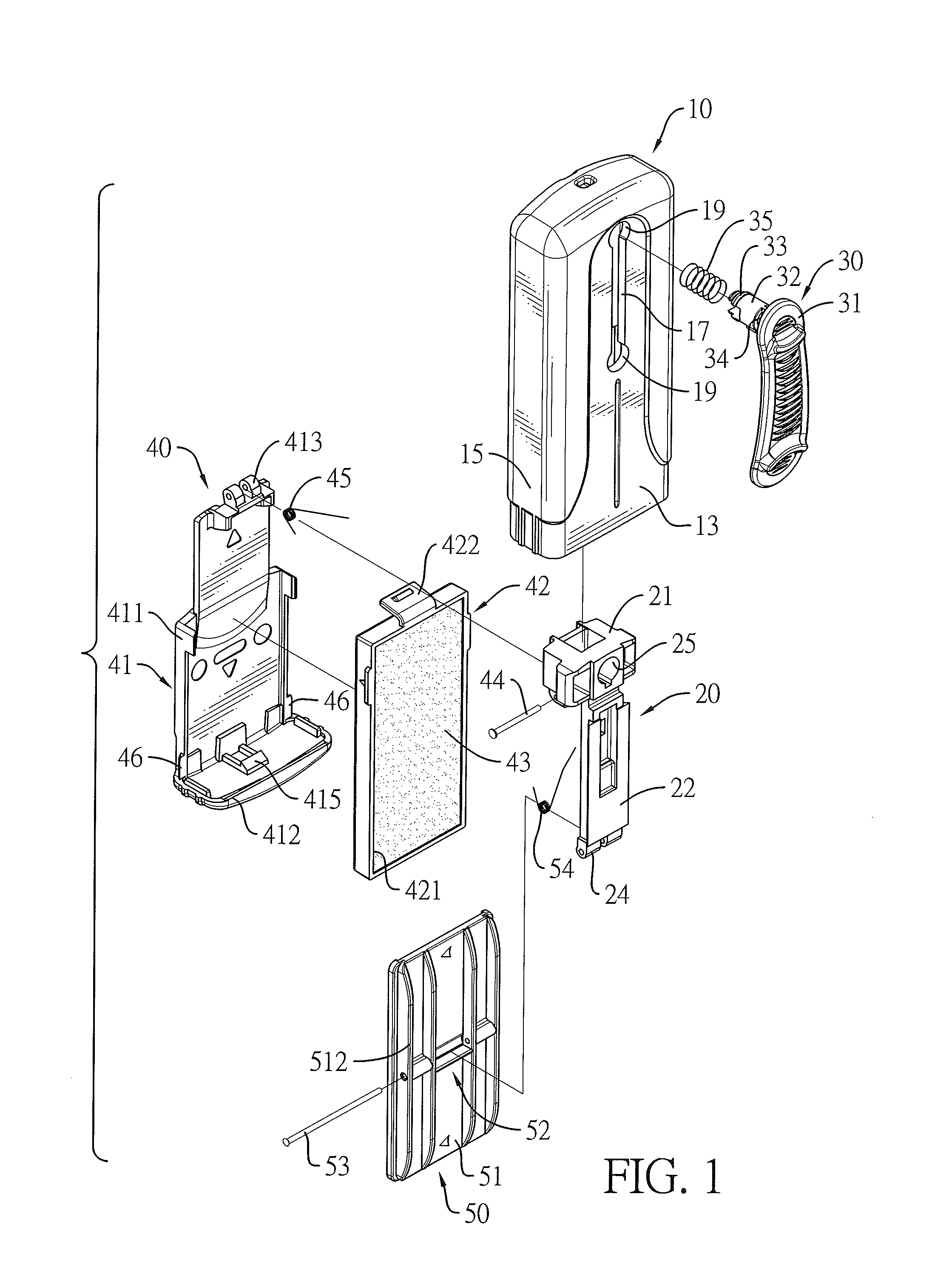
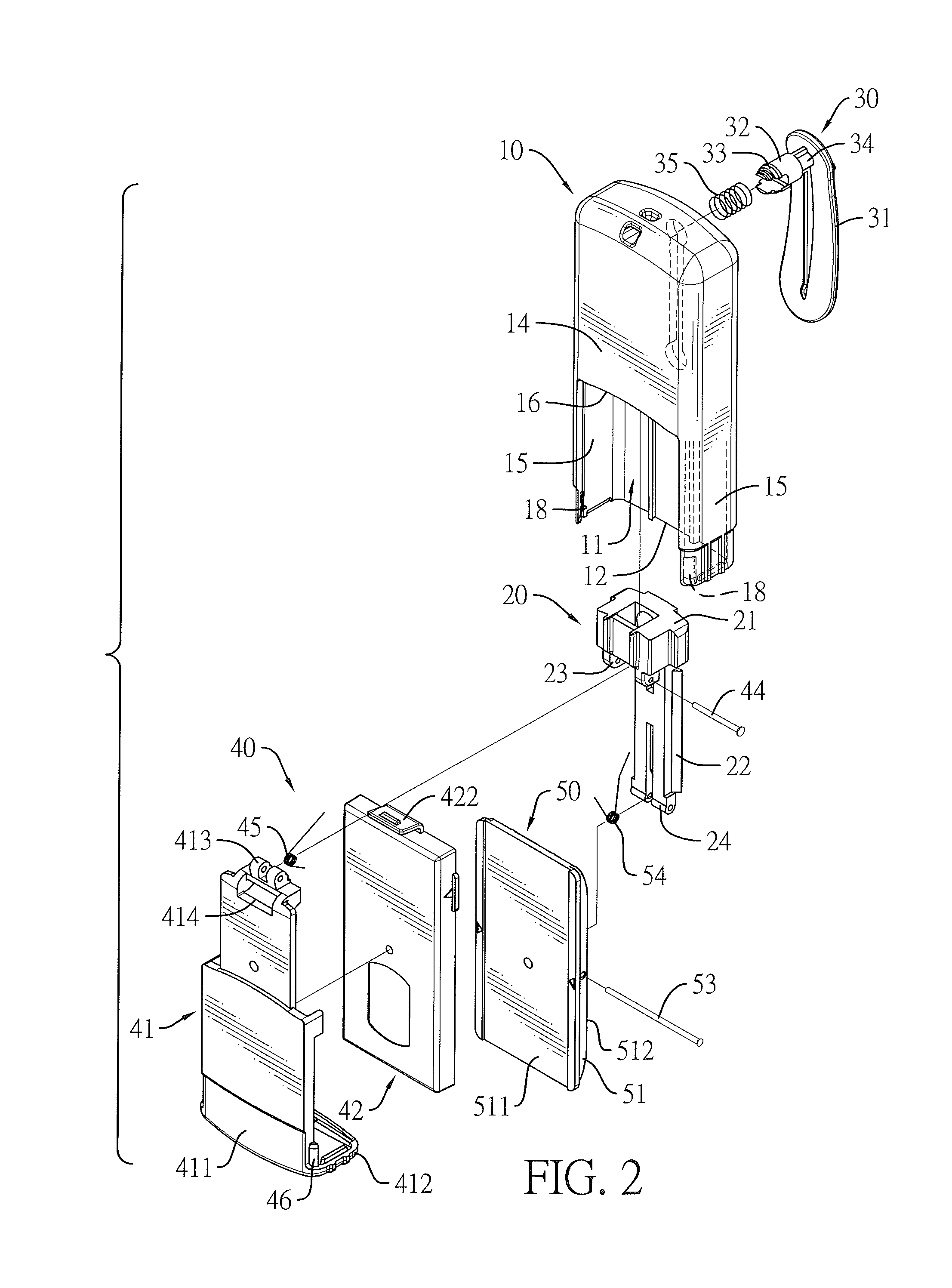
[0020]With reference to FIGS. 1 and 2, a portable stamp in accordance with the present invention comprises a stamp housing 10, a driving member 20, an operating member 30, an ink member 40, and a stamp seat 50.

[0021]With reference to FIGS. 1 to 3, the stamp housing 10 has a mounting chamber 11, a lower opening 12, a first sidewall 13, a second sidewall 14, and two lateral sidewalls 15.

[0022]The mounted chamber 11 is formed inside the stamp housing 10. The lower opening 12 is formed on a bottom of the stamp housing 10 and communicates with the mounting chamber 11.

[0023]The first sidewall 13 has a guiding slot 17 and two mounting holes 19. The guiding slot 17 extends longitudinally, communicates with the mounting chamber 11, and has two ends. The mounting holes 19 are respectively formed at and enlarged relative to the two ends of the guiding slot 17, and communicate with the guiding slot 17. The second sidewall 14 is opposite to the first sidewall 13 and has a moving recess 16. The m...


PUM


Abstract

A portable stamp has a stamp housing, and a driving member, an ink member with an ink pad and a stamp seat for mounting a stamp pad mounted in the stamp housing. An operating member is mounted through a guiding slot of the stamp housing and is connected to the driving member. Each of the ink member and the stamp seat is pivotally connected to the driving member via a pivot rod and a torsion spring. By pushing the driving member, the ink member and the stamp seat can be driven to selectively pivot out of the stamp housing or be folded in the stamp housing. When the portable stamp is folded, a stamping surface of the stamp pad that is mounted on the stamp seat is sure to touch the ink pad of the ink member and be coated with the ink uniformly.

Description

BACKGROUND OF THE INVENTION[0001]1. Field of the Invention[0002]The present invention relates to a stamp, especially to a portable stamp that can be folded and unfolded and allows a user to carry along.[0003]2. Description of the Prior Art(s)[0004]A conventional portable stamp comprises a stamp housing, and a driving member, an ink member and a stamp seat mounted in the stamp housing. An operating member is mounted through a sidewall of the stamp housing and is connected to the driving member. Each of the ink member and the stamp seat is pivotally mounted on the driving member via a pivot rod and a torsion spring. The ink member has an ink pad. The stamp seat is used for mounting a stamp pad that has a stamping surface. When the conventional portable stamp is folded, the ink member and the stamp seat are received in the stamp housing. Thus, a room that the conventional portable stamp occupies can be reduced, and the stamp pad can touch the ink pad of the ink member to be coated with...

Claims


Application Information

Patent Timeline
IPC IPC(8): B41K1/42B41K1/56B41K1/40B41F31/00B41K1/50B43K29/00B43K29/013
CPCB41K1/40B41K1/56B41K1/50B43K29/00B43K29/013B41K1/42B41K1/006B41K1/02B41K1/52
Inventor SHIH, WEN-JER
Owner SUN SAME ENTERPRISES
Why Eureka
Eureka Blog
Learn More