Hypercentric lens assembly with high numeric aperture aspheric element

Active Publication Date: 2016-03-01
LUSTER SPENCER D
View PDF2 Cites 4 Cited by
  • Summary
  • Abstract
  • Description
  • Claims
  • Application Information

AI Technical Summary

Benefits of technology

[0006]This invention relates to an imaging hypercentric lens assembly comprised of a First Lens Group that includes: 1) At least a first high NA (0.40 or greater) aspheric lens element followed by 2) at least a second lens element that converges the light emitted from the first element to a small spot. It is further comprised of a Second Lens Group whose entrance pupil is placed at t

Problems solved by technology

Such aspheric refractive surfaces, however, have been limited to relatively low numeric apertures (NA) of less than approximately 0.30 when used for finite conjugate ratio imaging, especially of objects whose size is not considerably smaller than th

Method used


Image

  • Hypercentric lens assembly with high numeric aperture aspheric element
  • Hypercentric lens assembly with high numeric aperture aspheric element
  • Hypercentric lens assembly with high numeric aperture aspheric element

Examples


Example

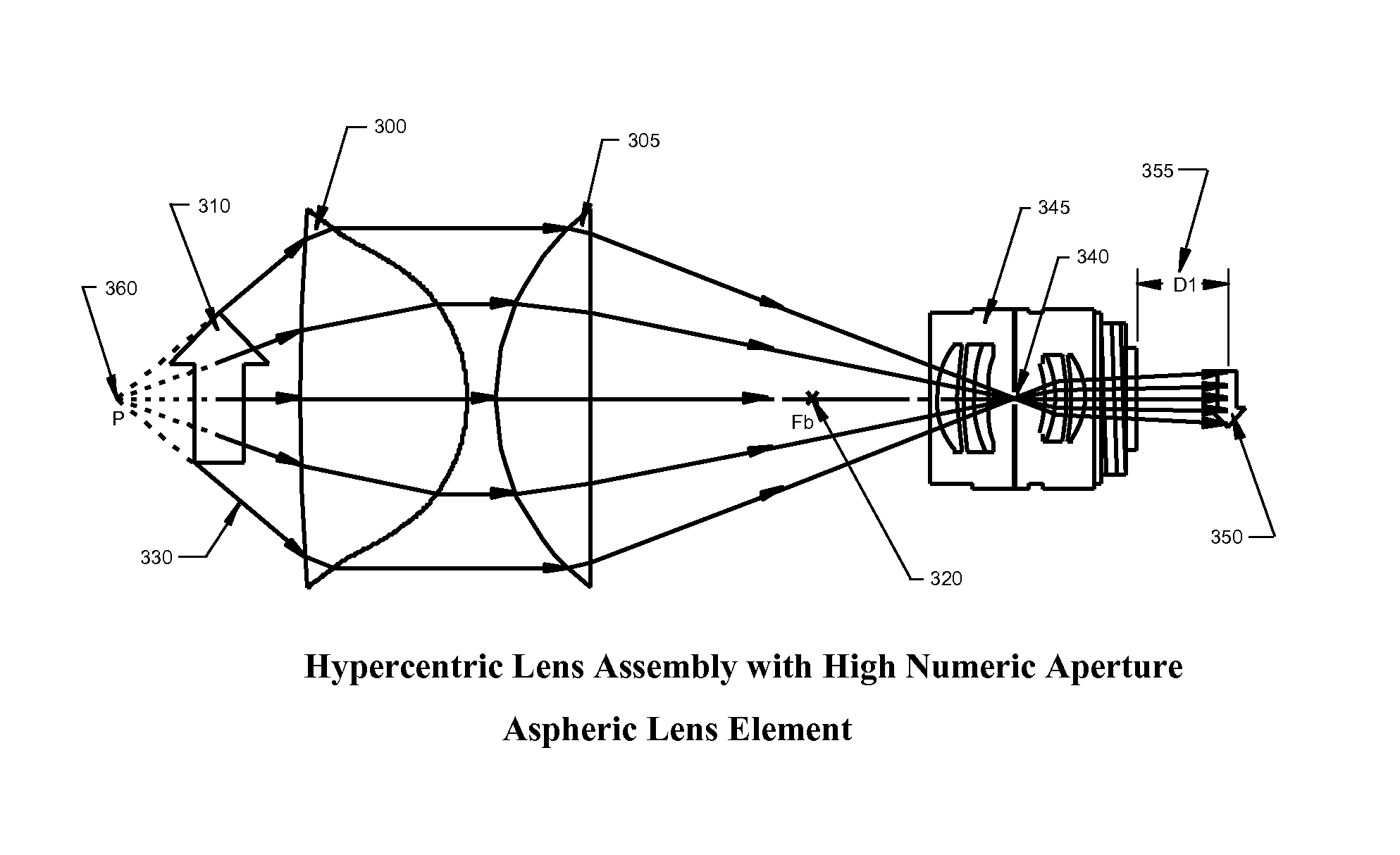
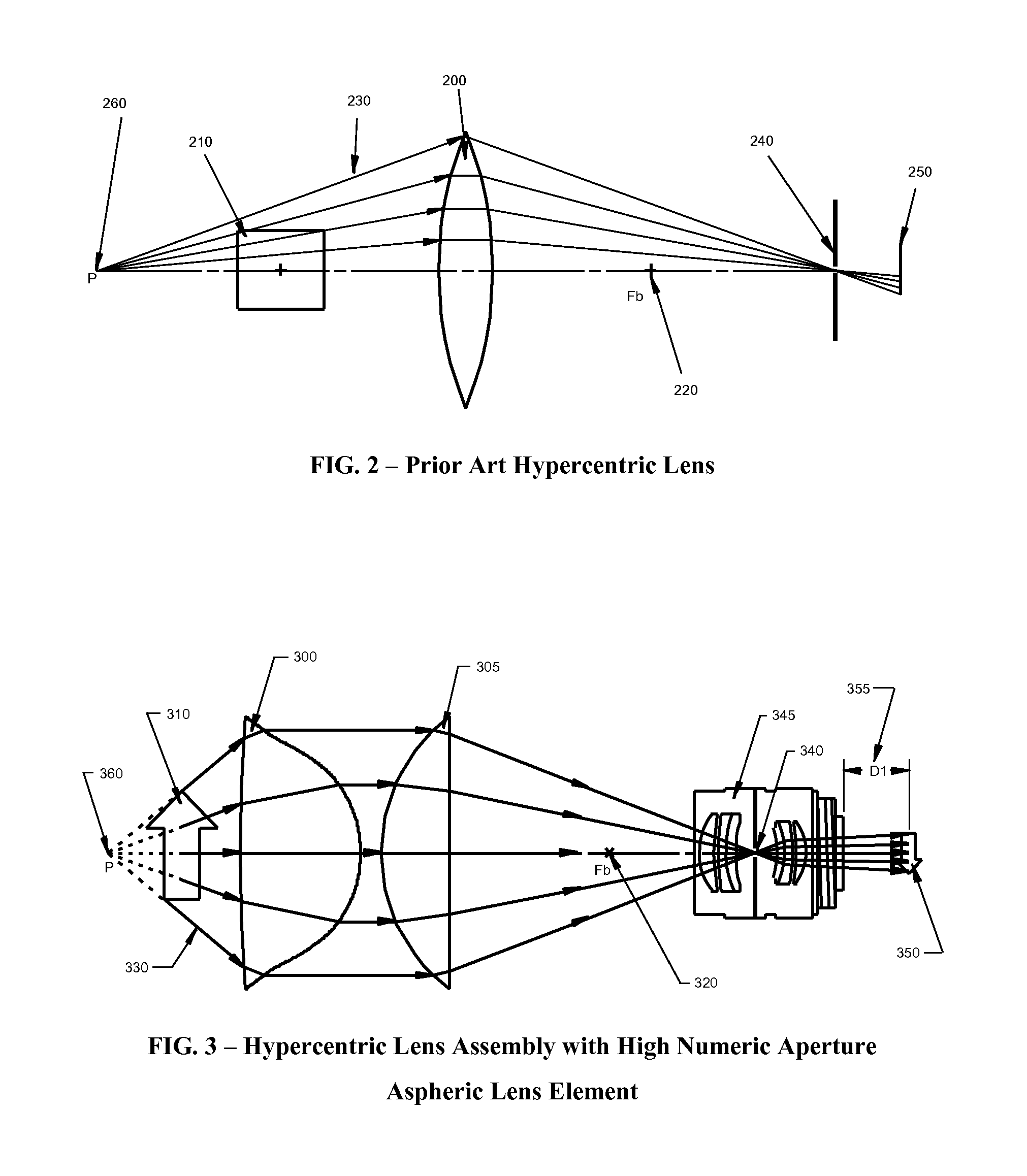
DETAILED DESCRIPTION OF THE DRAWINGS

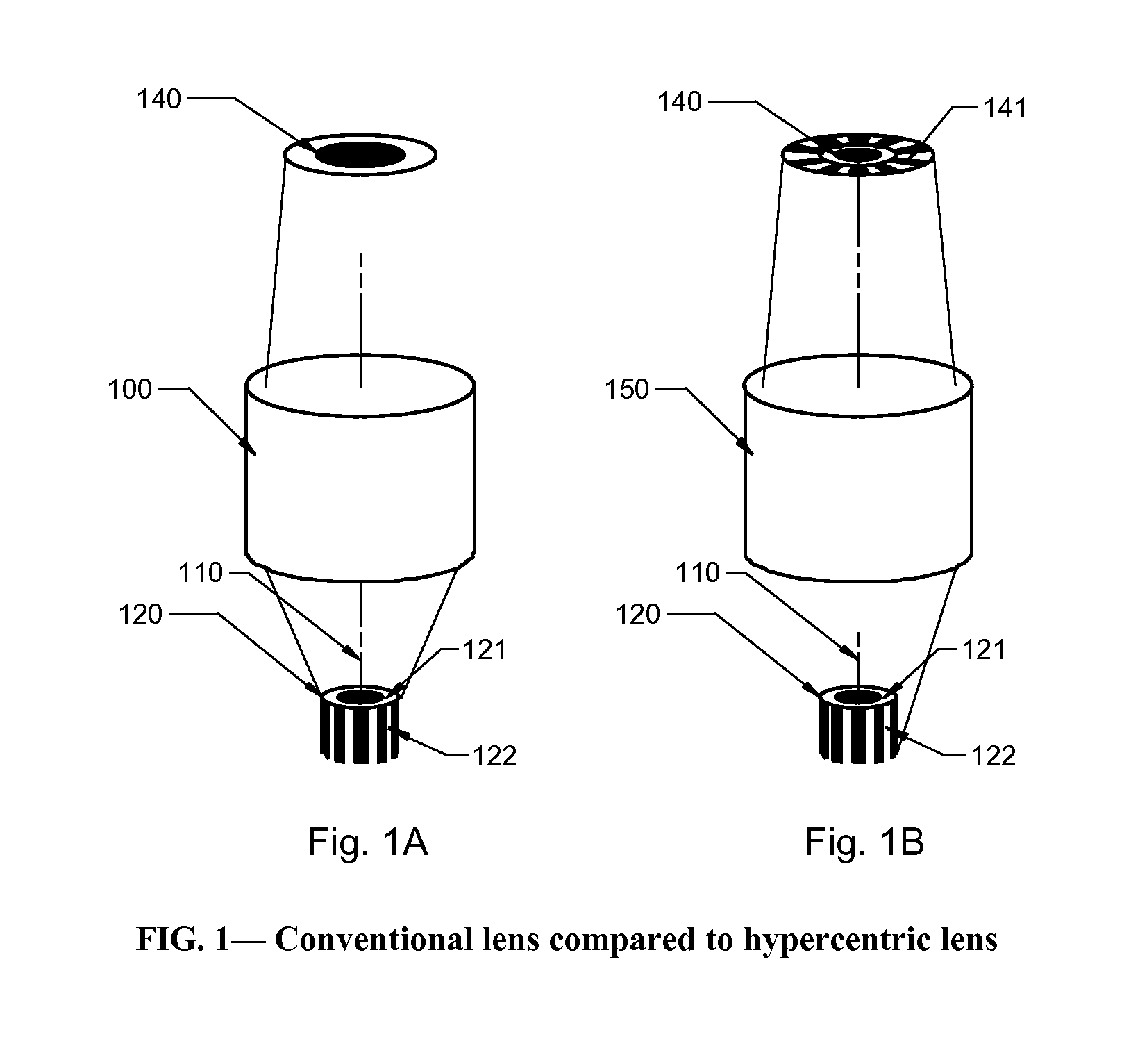
[0012]FIG. 1A shows a conventional lens (100), such as a microscope objective, having an optical axis (110). Said lens 100 views a cylindrical object (120) having a top (121) that is essentially perpendicular to the optical axis, and a side (122) that is parallel to the optical axis. The lens 100 forms an image (140) only of the top (121) of the object.

[0013]FIG. 1B shows a hypercentric lens (150) having an optical axis 110. Said lens 150 views a cylindrical object 120 having a top 121 that is essentially perpendicular to the optical axis and a side 122 that is parallel to the optical axis. The lens 150 forms an image 140 of the top 121 as well as the side 122 of the object.

[0014]FIG. 2 shows an example of a prior art hypercentric lens system in which a spherical lens element (200) receives rays of light (230) from an object (210) and re-directs them toward a small pinhole or aperture (240) that is located beyond the back focus (220) of the lens. ...


PUM


Abstract

An imaging hypercentric lens assembly comprising of a First Lens Group that includes: 1) At least a first high NA (0.40 or greater) aspheric lens element followed by 2) at least a second lens element that converges the light emitted from the first element to a small spot. It is further comprised of a Second Lens Group whose entrance pupil is placed at the same position as said small light spot. The Second Lens Group serves to refocus the light and form an image of an object placed in front of the First Lens Group. In this combination, the present invention allows high NA aspheric lens elements to produce good quality images of objects whose size is not limited to being considerably smaller than the diameter of the clear aperture of the high NA aspheric lens element.

Description

RELATED APPLICATIONS[0001]Priority is claimed under 35 U.S.C. 120 from U.S. patent application Ser. No. 13 / 663,170 filed Oct. 29, 2012, which claims priority under 35 U.S.C. 119(e) from U.S. Provisional Application Ser. No. 61 / 552,685 filed Oct. 28, 2011, all incorporated herein by reference.BACKGROUND OF THE INVENTION[0002]A hypercentric or pericentric lens is one in which a converging view of an object is achieved. This is as opposed to the more conventional diverging view lens common in most optical systems (including human vision), or for parallel (non-diverging, non-converging) view telecentric lenses.[0003]Furthermore, at least two other combined properties distinguish a hypercentric lens from other types. The first property is that the entrance pupil (which may be defined as the image of the physical aperture stop as “seen” from the front of the lens) is located in front of the physical lens. The second is that such a lens may observe surfaces that are parallel to the optical...

Claims


Application Information

Patent Timeline
IPC IPC(8): G02B3/02G02B13/18
CPCG02B13/18G02B13/22G02B13/24G02B21/0016
Inventor LUSTER, SPENCER, D.
Owner LUSTER SPENCER D
Why Eureka
Try Eureka