Image forming apparatus

a technology of forming apparatus and forming tube, which is applied in the direction of electrographic process, instruments, transportation and packaging, etc., can solve the problems of difficult extraction of paper sheets, and achieve the effect of easy extraction

Active Publication Date: 2016-03-08
SHARP KK
View PDF26 Cites 2 Cited by
  • Summary
  • Abstract
  • Description
  • Claims
  • Application Information

AI Technical Summary

Benefits of technology

[0025]According to the present invention, the pulling member and the movable wiring are arranged inside the housing at the upper side of the second surface. Therefore, a height of the first surface, which is a bottom surface of the image reading unit, from the discharge tray can be raised up to a height restricted by the scanning body. Further, by raising the bottom of the first surface, the discharge space on the discharge tray can be expanded in the height direction. Accordingly, even if a small-sized paper sheet is discharged on the discharge tray, the paper sheet discharged to the back side of the discharge tray (the discharge unit side) can be easily taken out. Additionally, the apparatus itself can be downsized (in particular, thinned).

Problems solved by technology

However, narrowing down the sheet discharge space causes a problem that a paper sheet is difficult to be extracted.
Accordingly, there is a problem that narrowing the sheet discharge space making the extraction of the paper sheet more difficult.

Method used


Image

  • Image forming apparatus
  • Image forming apparatus
  • Image forming apparatus

Examples


Embodiment Construction

[0036]Embodiments of the present invention will be described below by referring to the accompanying drawings.

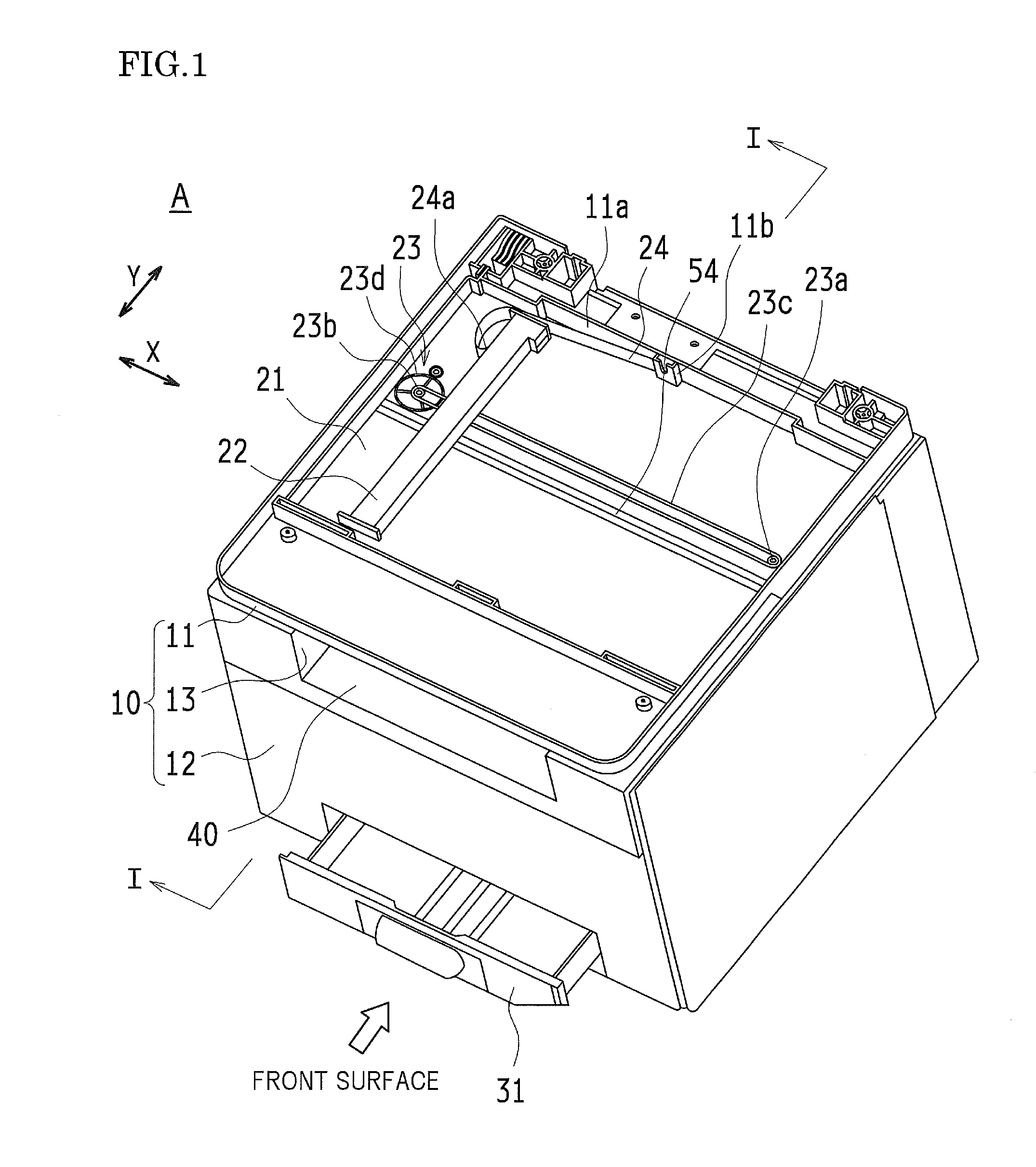
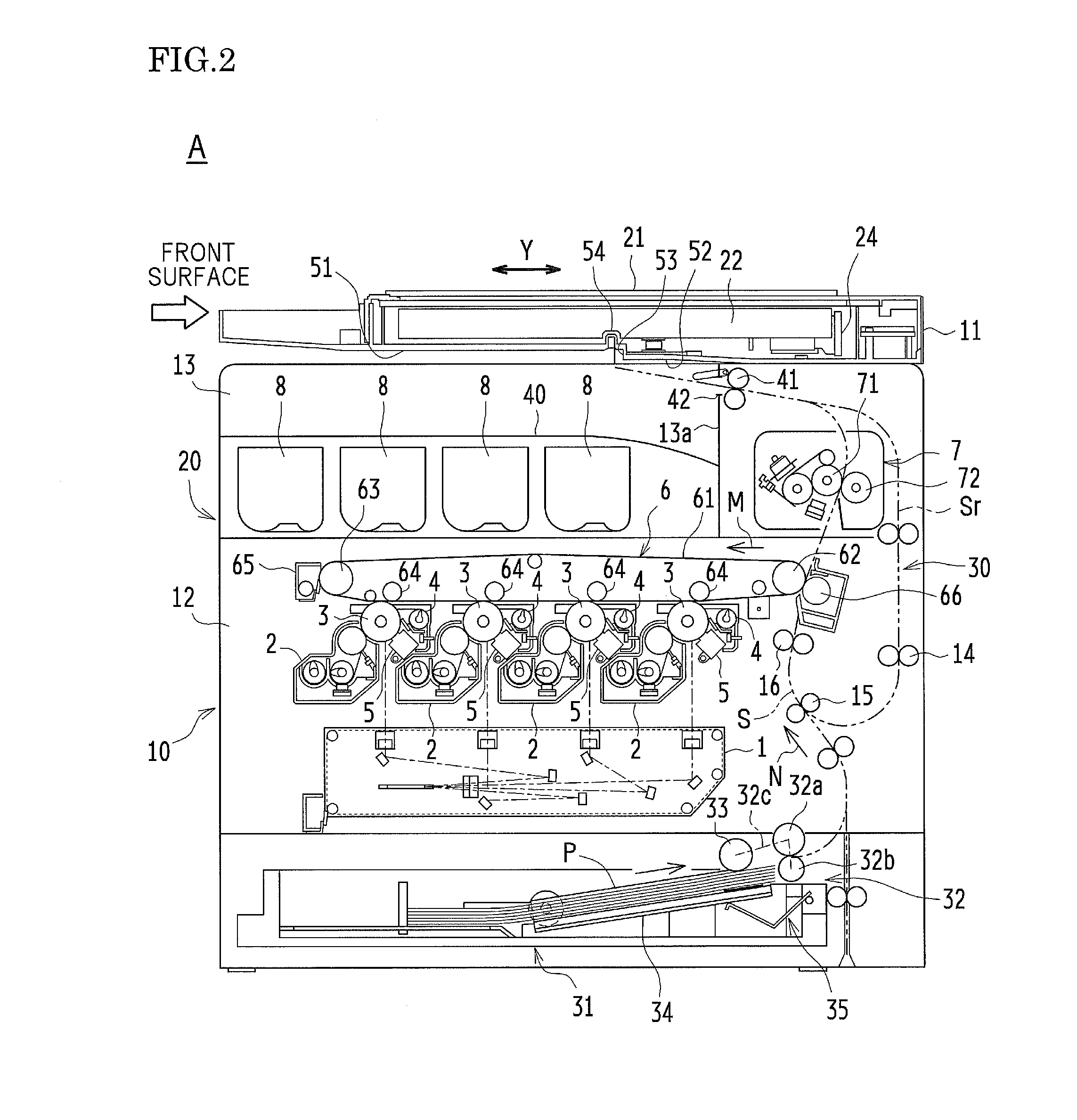
[0037]FIG. 1 is a perspective view of an image forming apparatus of the present invention. FIG. 2 is a schematic cross-sectional view of when the image forming apparatus of the present invention is viewed from a side surface (a schematic cross-sectional view taken along the line I-I of FIG. 1). FIG. 3A and FIG. 3B are perspective views of an image capturing housing unit. Note that, in the embodiment, the illustration of an original reading apparatus that reads documents in automatic feeding is omitted.

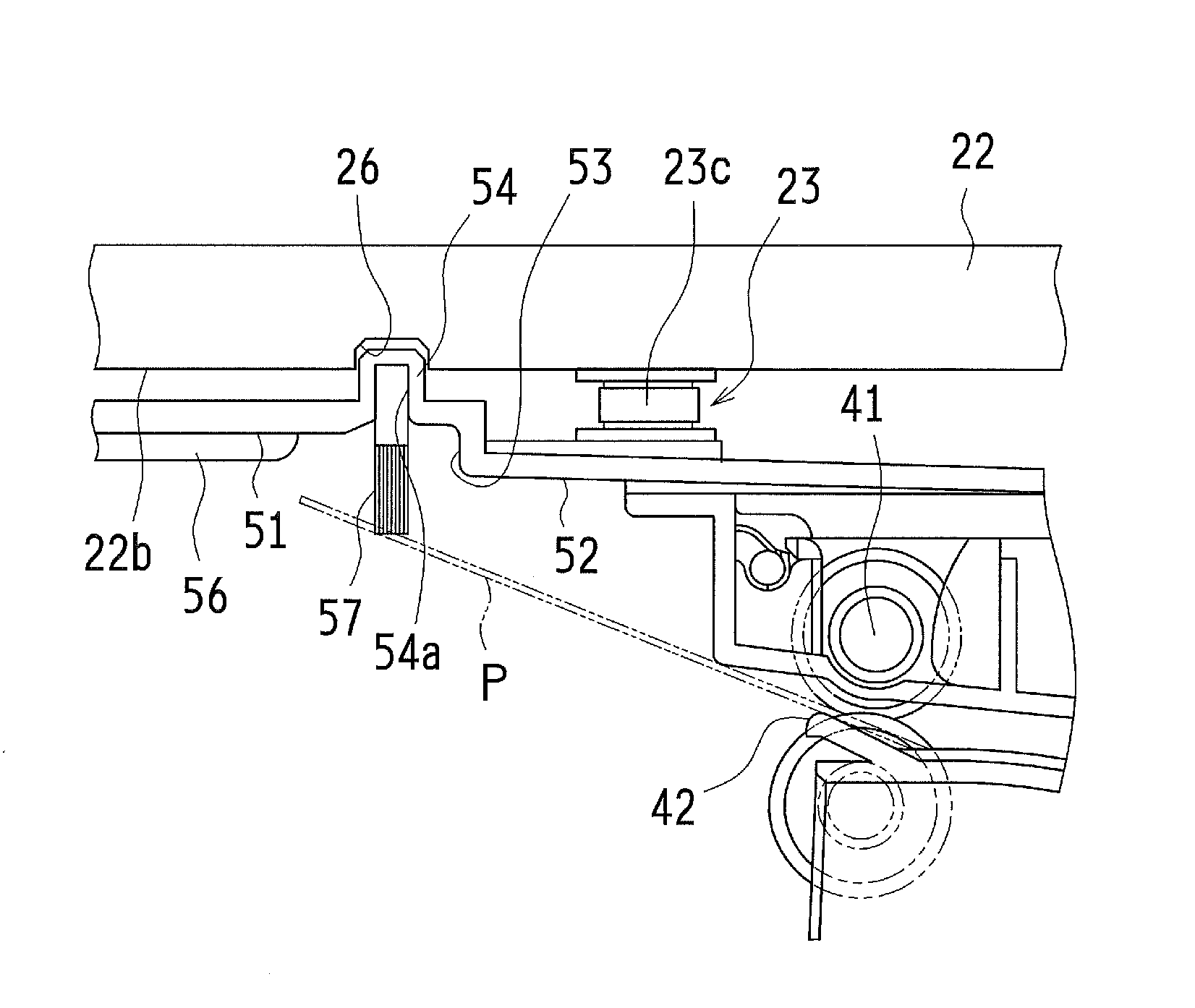
[0038]An image forming apparatus A illustrated in FIG. 1 and FIG. 2 is an image forming apparatus of an in-body paper discharging type. The image forming apparatus A includes an in-body paper discharge space portion 13 between an image capturing housing unit 11 and an image forming housing unit 12 of an apparatus main body 10. The in-body paper discharge space portion 13 has a U...


PUM

PropertyMeasurementUnit
sizeaaaaaaaaaa
thicknessaaaaaaaaaa
heightaaaaaaaaaa

Abstract

An image forming apparatus includes an image reading unit, an image forming unit, a discharge unit, and a discharge tray. The image reading unit is configured to read a document placed on a document placement table by moving and scanning of a scanning body in a sub-scanning direction. The image forming unit is configured to form an image read by the image reading unit on a paper sheet. The discharge unit is configured to discharge the paper sheet on which an image is formed by the image forming unit to a direction perpendicular to the sub-scanning direction. The discharge tray is on which the paper sheet from the discharge unit is to be placed with a space portion at a lower side of the image reading unit. A bottom surface of a housing of the image reading unit facing the discharge tray is constituted of a first surface and a second surface. The first surface is a surface at a front side of the discharge unit in a discharging direction and high with respect to the discharge tray. The second surface is a surface at a back side of the discharge unit in the discharging direction lower than the first surface with respect to the discharge tray. A pulling member and / or a movable wiring are / is arranged at an upper side of the second surface inside the housing. The pulling member is configured to move the scanning body back and forth in the sub-scanning direction. One end portion of the movable wiring is secured to the scanning body.

Description

TECHNICAL FIELD[0001]This application is the U.S. national phase of International Application No. PCT / JP2013 / 060488 filed 5 Apr. 2013 which designated the U.S. and claims priority to Japanese Patent Application No. 2012-093122 filed 16 Apr. 2012, the entire contents of each of which are hereby incorporated by reference.[0002]The present invention relates to an image forming apparatus of an in-body paper discharging type, more specifically, relates to an image forming apparatus with a structure where a paper sheet on which an image has been formed by an image forming unit is discharged in a direction perpendicular to a sub-scanning direction, a movement direction of a scanning body.BACKGROUND ART[0003]Recently, demands of space-saving, downsizing, and thinning of an image forming apparatus have been further increased. In response to these demands, it is possible to thin an image forming apparatus of an in-body paper discharging type that includes a discharge tray between an image rea...

Claims


Application Information

Patent Timeline
Patent Type & Authority Patents(United States)
IPC IPC(8): G03G15/00B65H31/00B41J29/13B65H29/14B65H29/52H04N1/00
CPCG03G15/6552B41J29/13B65H29/14B65H29/52B65H31/00G03G15/00H04N1/0083H04N1/00527H04N1/00543B65H2301/5133B65H2405/115B65H2801/06H04N1/0057G03G15/60G03G21/1619H04N1/00522H04N1/00631H04N1/00795H04N1/1026H04N2201/0082
Inventor NAKANISHI, KENJIIMOTO, MASAHIROSUTO, YASUHIROFUKUTOME, SHOHICHIYAMANAKA, HISASHIYOSHIMOTO, MITSUHARU
Owner SHARP KK
Why Eureka
Try Eureka