
Connector

a technology of connecting rods and connectors, applied in the direction of electrical equipment, coupling device connections, support structure mounting, etc., can solve the problems of inefficient space use, limited space on the edges of circuit boards, and requiring the reduction of the number of electrical terminals

Active Publication Date: 2016-03-08
SOURIAU JAPAN
View PDF27 Cites 0 Cited by
  • Summary
  • Abstract
  • Description
  • Claims
  • Application Information

AI Technical Summary

Benefits of technology

[0013](1) The connector according to the present invention comprises a connecting member connected to a turn axis portion for turning the ejector so as to secure the circuit board and the base portion of the connector body, enabling the base portion of the connector body and the ejector to be assembled integrally, so that the space for attaching the ejector and the circuit board in a conventional connector can be eliminated, as a result of which the number of electrical terminals in the connector can be maintained and complicated circuit arrangements can be supported.(2) The connector according to the present invention has a connecting member that is integrally molded with the panel using a conductive material, so that the number of components can be reduced and the connector can be easily assembled, in addition to the fact that, for example, the frame ground of the unit wiring rack can be connected to a ground line of the circuit board via the panel, the connecting member and the conductive turn axis portion of the ejector, as a result of which a shielding effect can be achieved with respect to the electrical terminals of the connector.(3) The connector according to the present invention has the frame, the panel and the connecting member connected to at least one wire in the circuit board through the turn axis portion, so for example, the conductive frame of a counterpart connector connected to a ground line can be electrically connected to the frame of the connector according to the present invention connected to the ground line of the circuit board, as a result of which an electrically stable connector can be offered.(4) The connector according to the present invention has a connecting member integrally molded with the base portion of the connector body, enabling the connecting member to be eliminated, thereby reducing the number of components and making assembly of the connector easier.(5) The connector according to the present invention has a connecting member further comprising a connecting portion with the frame, enabling connecting components such as screws or bolts to be connected from different directions with a single connecting member, as a result of which a small connector that can be easily assembled and achieving the purpose of the present invention can be offered.

Problems solved by technology

Since unit wiring racks and circuit boards are standardized, if the conventional connector terminal sizes and inter-terminal distance are used, there will be extremely limited space on the edges of the circuit boards on which the connectors are mounted, requiring the number of electrical terminals to be decreased.
They therefore make inefficient use of the space at the edges of the circuit board onto which a connector is to be mounted, and have a complicated mounting structure using many components.

Method used


Image

  • Connector
  • Connector
  • Connector

Examples


embodiment 1

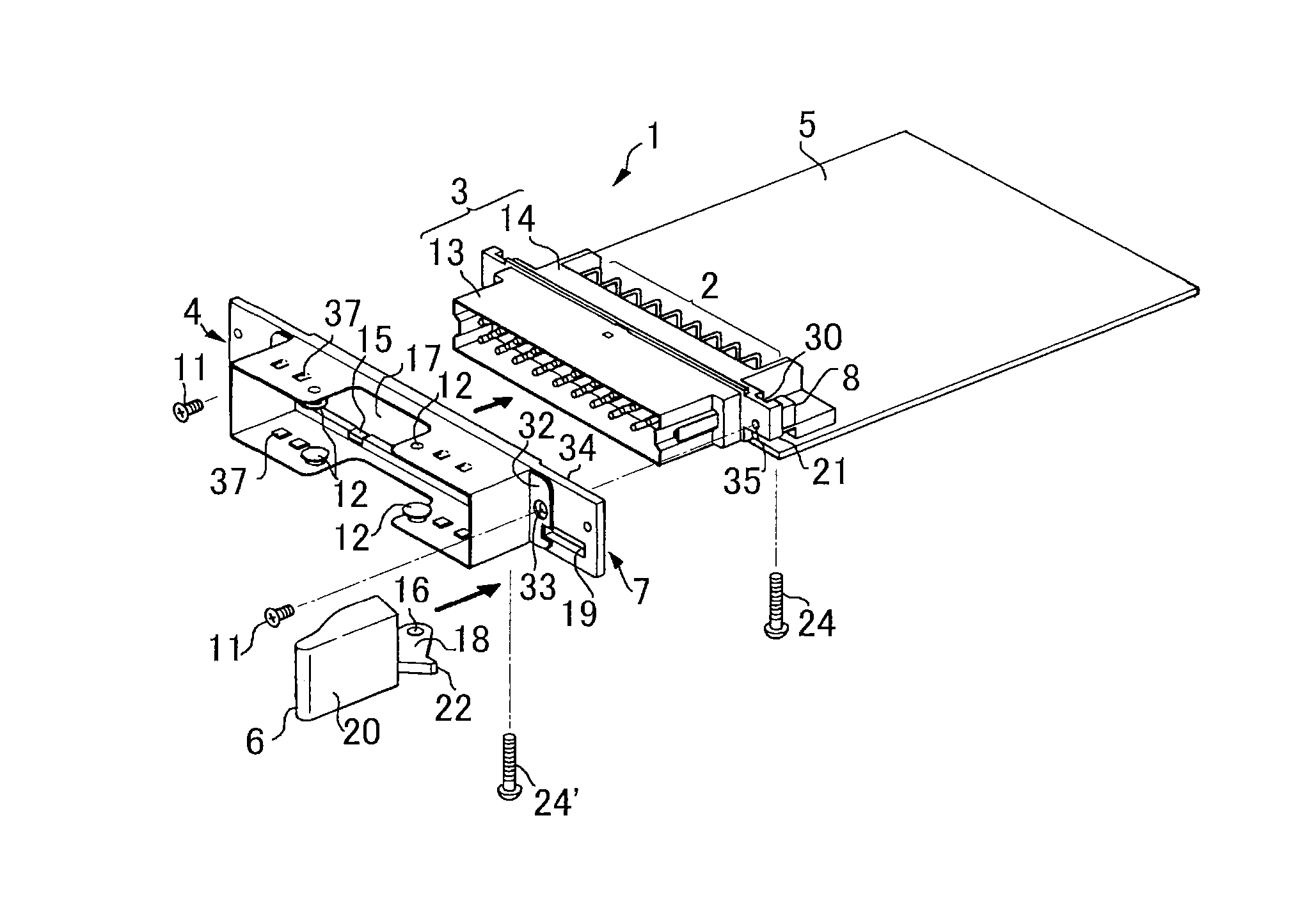
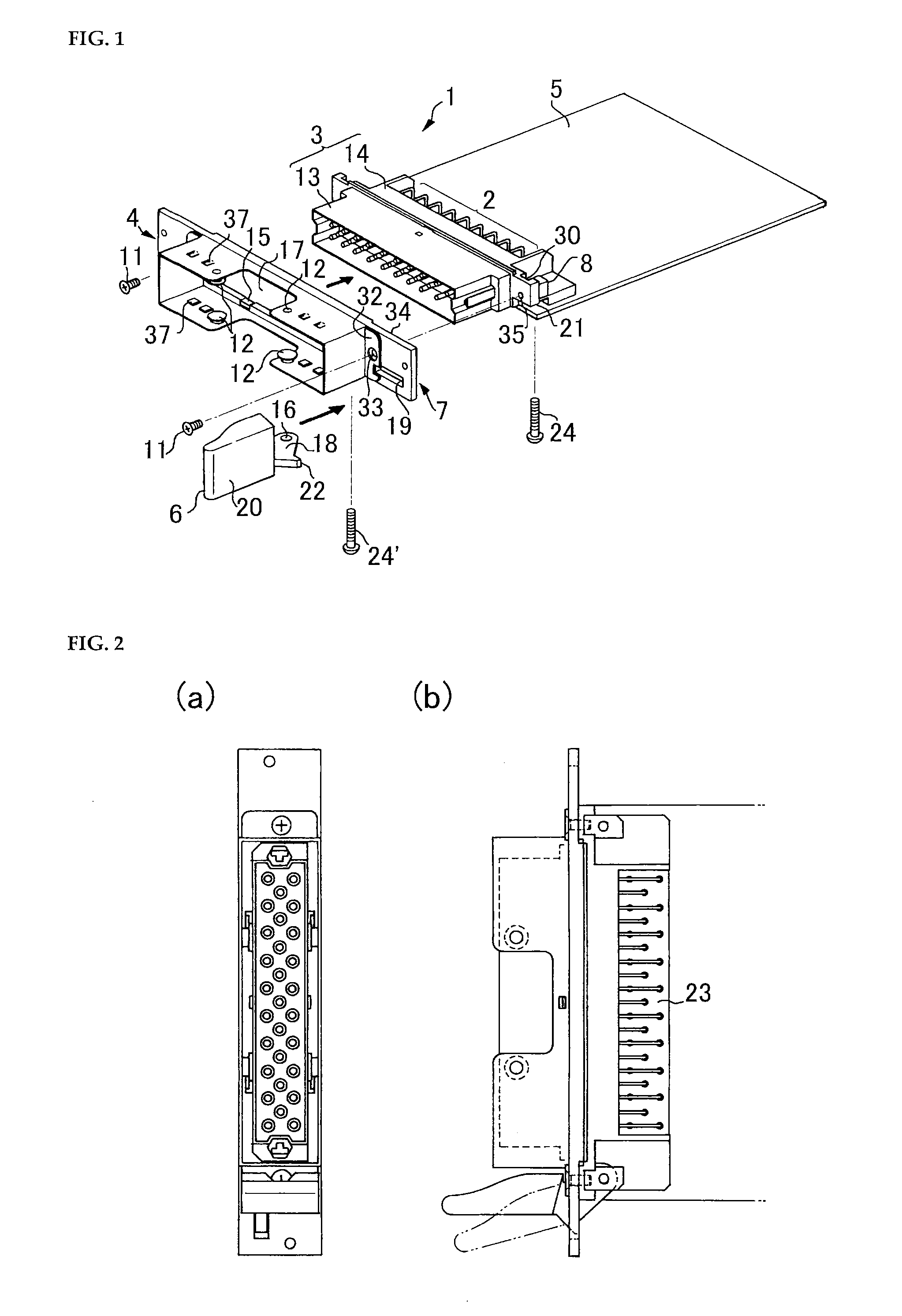
[0029]FIG. 1 is an exploded perspective view of the panel circuit board 1 of the present invention which is to be inserted into a unit wiring rack or the like for storage.

[0030]FIG. 2(a) is a front view with the assembly of the panel circuit board 1 shown in FIG. 1 completed, and FIG. 2(b) is a plan view.

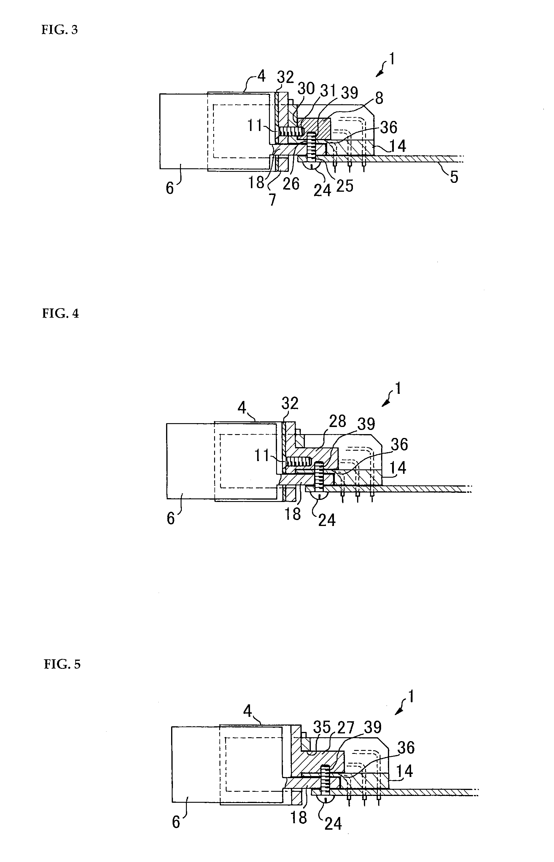
[0031]FIG. 3 is a side view from the ejector side of the panel circuit board 1 of FIG. 1 corresponding to Embodiment 1 and Embodiment 2, showing the connection arrangement between the frame 4, panel 7, cuboid block 8 and base portion 14 of the connector body 3.

[0032]FIG. 7 is an enlarged side view showing the details of a screw 11 and screw 24 screwed into the cuboid block 8 in FIG. 3.

[0033]A unit wiring rack is used for housing computer equipment and communications equipment, and as shown in FIG. 13, enables simultaneous insertion of a plurality of substrates in order to make efficient use of circuit wiring space.

[0034]A panel circuit board 1 comprises a circuit board 5, a connecto...

embodiment 2

[0050]Embodiment 2 differs from Embodiment 1 in that the frame 4, panel 7, cuboid block 8, screw 11 and screw 24 are limited to conductive materials. In this case, as can be seen with reference to FIG. 3, like Embodiment 1, when assembly of the panel circuit board 1 has been completed, the frame 4 is electrically connected to the panel 7 by surface contact via the claw portion 15 or the tab 32, the tab 4 is electrically connected to the cuboid block 8 via the screw 11, and the cuboid block 8 is electrically connected to predetermined wires of the circuit board 5 through the screw 24 (turn axis portion of ejector). Additionally, if the screw head of the screw 24 is in contact with a ground line of the circuit board 5, then the frame 4 is electrically connected to the ground line of the circuit board 5.

[0051]As a result, when the connector portion shown in FIG. 1 is mated with a counterpart connector portion not shown in the drawings, the raised portions 37 formed on the frame 4 so as...

embodiment 3

[0053]Embodiment 3 differs from Embodiments 1 and 2 in that the panel 7 and cuboid block 8 in FIG. 3 are formed by integrally molding with a non-conductive or conductive material. FIG. 4 is a side view showing the arrangement of Embodiment 3, as seen from the ejector side of the panel circuit board 1 shown in FIG. 1. In FIG. 4, the integral portion 28 integrally formed from the panel 7 and the cuboid block 8 is indicated by the hatched portion.

[0054]FIG. 8 is an enlarged side view showing the details when the screw 11 and screw 24 are screwed into the hatched portion 28 of FIG. 4.

[0055]In Embodiment 3 as well, if the integral portion 28 is a conductive material, when assembly of the panel circuit board 1 has been completed, the frame 4 will be electrically connected to the integral portion 28 integrally formed from the panel 7 and the cuboid block 8 by a direct connection via the claw portion (not shown) of the frame 4 or by surface contact by means of the tab 32, whereby the integr...


PUM


Abstract

A connector mounted to a circuit board to be inserted into a storage destination, and configured to include: a connector body including a housing part for housing an electric terminal connected to a predetermined wire of the circuit board, and a base part connected to the housing part; a panel including an opening which is formed in a pair of opposed surfaces and through which the housing part can be inserted; an ejector for detaching the circuit board from an insertion destination by turning; and a connection member connected to a turning shaft part for turning the ejector to fasten the circuit board and the base part of the connector body. The connector can be mounted, together with the ejector, to a compact circuit board corresponding to a compact unit wire rack and can be efficiently mounted in a saved space.

Description

TECHNICAL FIELD[0001]The present invention relates to a connector for connecting an electrical circuit board of the type inserted in a unit wiring rack (subrack) or the like, the connector being mounted on a panel for sealing the insertion port of the unit wiring rack.BACKGROUND ART[0002]In recent years, the unit wiring racks used in computer systems have circuit boards mounted by insertion into the unit wiring rack with a panel as a lid. In this case, the input and output of electrical signals may be performed via a connector mounted on the panel and connected to the circuit board (front panel type).[0003]FIG. 13 shows a plurality of panel circuit boards comprising a panel and a connector mounted on a circuit board, inserted into a unit wiring rack. When the storage space in the unit wiring rack is sufficiently large as shown in FIG. 13, large circuit boards can be used. In that case, because conventional circuit boards are large and the edges are long enough in the longitudinal di...

Claims


Application Information

Patent Timeline
Patent Type & Authority Patents(United States)
IPC IPC(8): H01R12/57H01R13/629H01R12/70H01R12/72H05K7/14
CPCH01R13/62938H01R12/7005H01R12/724H01R13/62983H05K7/1409H01R12/71
Inventor OHNUKI, SHIGERUENOMOTO, KAZUO
Owner SOURIAU JAPAN
Learn More