Reducing temperature drift of an arrayed waveguide grating

a technology of arrayed waveguides and temperature drift, which is applied in the direction of optical waveguide light guides, instruments, optics, etc., can solve the problems of increasing optical delay, high electrical power consumption, and increasing awgs thermal sensitivity, and achieve the effect of lessening wavelength dri

Active Publication Date: 2016-03-15
LUMENTUM OPERATIONS LLC
View PDF19 Cites 3 Cited by
  • Summary
  • Abstract
  • Description
  • Claims
  • Application Information

AI Technical Summary

Benefits of technology

[0011]It is a goal of the invention to provide a quickly tunable and manufacturable temperature-compensated AWG capable of operating at a moderate electrical power consumption.
[0012]The present invention advantageously utilizes a micro-electro-mechanical system (MEMS) having a tiltable mirror for reflecting input light onto an input slab of an AWG. A MEMS controller is used to controllably tilt the MEMS mirror to compensate for temperature drifts of the AWG and / or to introduce controllable wavelength / frequency shifts. Low power consumption MEMS controllers are preferred, because they can be powered by an incoming light signal converted into electricity. Utilization of MEMS mirrors in AWG-based wavelength selective devices enables construction of manufacturable, tunable AWG devices with a reduced sensitivity to temperature drifts and mechanical vibration.
[0019]a controller electrically coupled to the temperature sensor and the tiltable MEMS mirror, and configured for varying the angle of tilt upon sensing the arrayed waveguide temperature change by the temperature sensor, so as to lessen a wavelength drift of the wavelength sub-beams induced by the temperature change.
[0020]Preferably, the MEMS controller has a low electrical power consumption, for example 10 mW or less, or even 1 mW or less. In one embodiment, an optical splitter splits a portion of the input optical beam to a photoelectric generator such as a photovoltaic cell, which powers the MEMS controller. A few milliwatt of incoming optical power can be sufficient to power the MEMS controller, thus providing thermal stabilization of the AWG without requiring a dedicated power line or an internal battery.
[0027](c) varying the first angle so as to lessen a wavelength drift of the wavelength sub-beams due to the change of temperature sensed in step (b).

Problems solved by technology

The gradually increasing waveguide length creates a gradually increasing optical delay on an inner surface of the output star coupler, which causes light at different wavelengths to couple into different output waveguides of the output star coupler.
One well-known drawback of AWGs is their thermal sensitivity.
One drawback is high electrical power consumption.
Another drawback is related to integration of thermally stabilized AWGs into a larger optical system.
Furthermore, a time constant required for temperature stabilization and temperature tuning of heated AWGs is relatively large, typically ranging from few tens of seconds to few minutes.
However, stress-induced birefringence increases polarization-dependent loss and polarization mode dispersion.
Detrimentally, the movable input waveguide in the Samiec device can cause the optical throughput of the AWG to be susceptible to shock and vibration, especially if the shock or vibration occurs in the PLC plane.
The Samiec and Delisle AWG devices have drawbacks of vibration sensitivity and a relatively slow response to an abrupt temperature change.
When the temperature changes quickly, thermal gradients between the PLC and the thermally expanding beams can cause time-varying wavelength drift.
This makes the Samiec and Delisle AWG devices more difficult to mass produce.

Method used


Image

  • Reducing temperature drift of an arrayed waveguide grating
  • Reducing temperature drift of an arrayed waveguide grating
  • Reducing temperature drift of an arrayed waveguide grating

Examples


Embodiment Construction

[0035]While the present teachings are described in conjunction with various embodiments and examples, it is not intended that the present teachings be limited to such embodiments. On the contrary, the present teachings encompass various alternatives and equivalents, as will be appreciated by those of skill in the art.

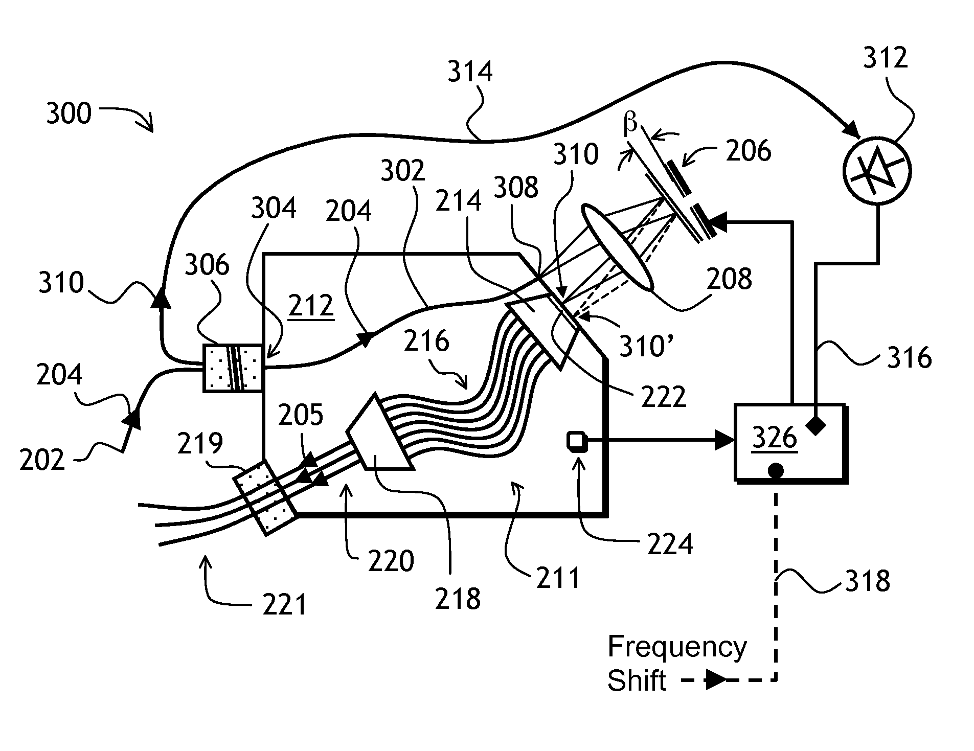
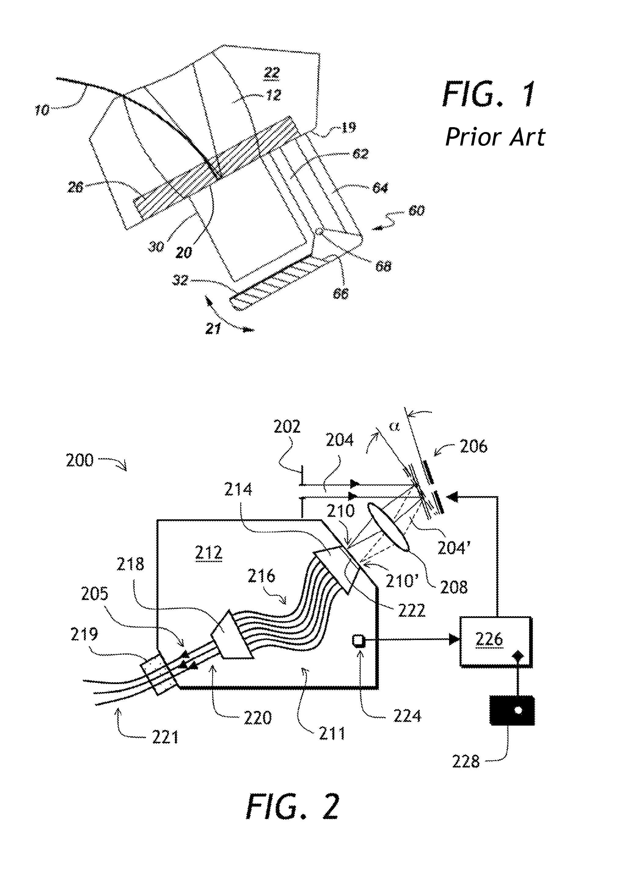
[0036]Referring to FIG. 2, a wavelength selective device 200 of the invention includes an input port 202 for inputting an optical beam 204. A tiltable MEMS mirror 206 is optically coupled to the input port 202. The tiltable MEMS mirror 206 reflects the optical beam 204 and redirects it towards a lens 208 optically coupled to the MEMS mirror 206. The lens 208 focuses the reflected optical beam 204 into a focal spot 210, which is displaceable by varying an angle of tilt α of the MEMS mirror 206. Another focusing element, such as a concave mirror, can be used in place of the lens 208.

[0037]The wavelength selective device 200 includes an AWG 211 implemented in a PLC chip 21...


PUM


Abstract

A wavelength selective device including an arrayed waveguide grating is disclosed. The wavelength selective device includes a MEMS mirror, which couples light from an input port to an elongate aperture of an input star coupler or slab of the arrayed waveguide grating. A controller tilts the MEMS mirror in response to a sensed temperature change of the arrayed waveguide grating, thereby lessening a sensitivity of the arrayed waveguide grating to the temperature change. The MEMS mirror can also be tilted to shift wavelengths of the wavelength channels of the arrayed waveguide grating by pre-defined amounts upon receiving a corresponding remote command.

Description

CROSS REFERENCE TO RELATED APPLICATIONS[0001]The present invention claims priority from U.S. patent application Ser. No. 61 / 717,424 filed Oct. 23, 2012, which is incorporated herein by reference.TECHNICAL FIELD[0002]The present invention relates to wavelength selective devices, and in particular to devices and methods for lessening thermal drift of arrayed waveguide gratings.BACKGROUND OF THE INVENTION[0003]Arrayed waveguide gratings (AWGs) are planar lightwave circuit (PLC) devices used for demultiplexing optical signals into individual wavelength channels. An AWG includes two slab-type star couplers, coupled to each other back-to-back via an array of planar waveguides of gradually increasing length. The gradually increasing waveguide length creates a gradually increasing optical delay on an inner surface of the output star coupler, which causes light at different wavelengths to couple into different output waveguides of the output star coupler. An AWG is a reciprocal device, that ...

Claims


Application Information

Patent Timeline
Patent Type & Authority Patents(United States)
IPC IPC(8): G02B6/34G02B6/12
CPCG02B6/12009G02B6/1203G02B6/12033
Inventor SHEN, JINXIFONDEUR, BARTHELEMYJIN, WENLINCHAPMAN, DAVID J.LIU, NIKI
Owner LUMENTUM OPERATIONS LLC
Why Eureka
Try Eureka