Cable-barriers

a technology of cable bars and cables, applied in the field of cable bars, can solve the problems of consuming a lot of time and being expensiv

Active Publication Date: 2016-03-29
VALMONT HIGHWAY TECH
View PDF11 Cites 0 Cited by
  • Summary
  • Abstract
  • Description
  • Claims
  • Application Information

AI Technical Summary

Benefits of technology

[0029]In preferred embodiments the cable and anchor portions may be configured so that the surface(s) / edge(s) which abut(s) the washer and nut of a respective cable is / are angled substantially between 91°-95° with regard to the longitudinal axis of the cable. The inventor has found this non-orthogonal angling of the washer relative to the direction of the tensional force of the cable, creates increased frictional pressure to help retain the tensioned cables within the slots.
[0033]Thus, preferred embodiments of the present invention may have a number of advantages over the prior art which can include:
[0036]A terminal post which is relatively inexpensive and quick to manufacture.
[0038]A terminal post which releases barrier cables from the top of the post. This effects a faster release near a vehicle's centre of gravity and thereby minimizes the risk of the anchor cables snagging on a vehicle.

Problems solved by technology

Conversely, the terminal post detailed in WO2007 / 129915 whilst effective in achieving its aims requires a separate anchor, body to be fabricated and attached to the upright member of the terminal post which is relatively time consuming and expensive.

Method used


Image

  • Cable-barriers
  • Cable-barriers
  • Cable-barriers

Examples


Embodiment Construction

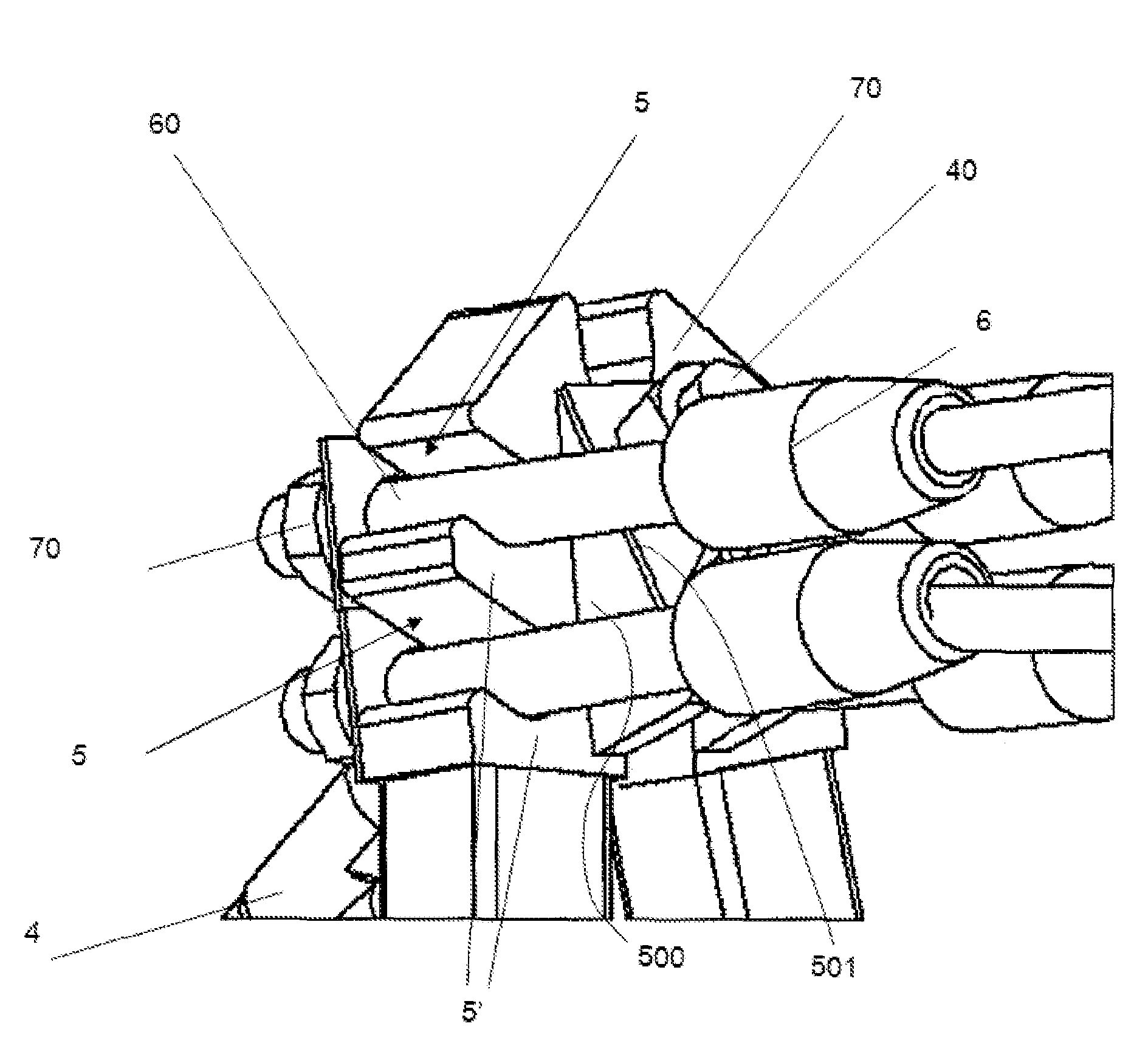
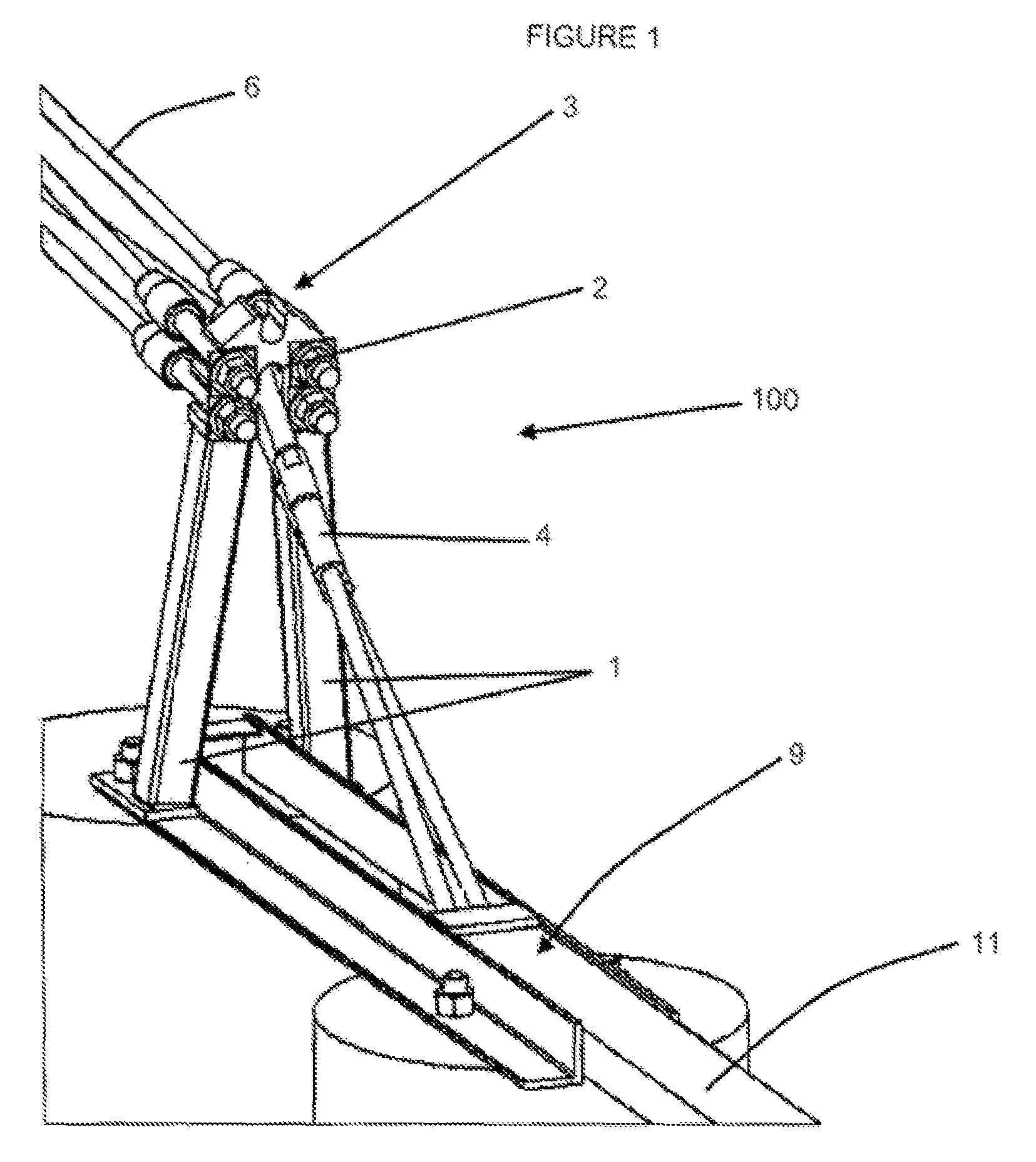
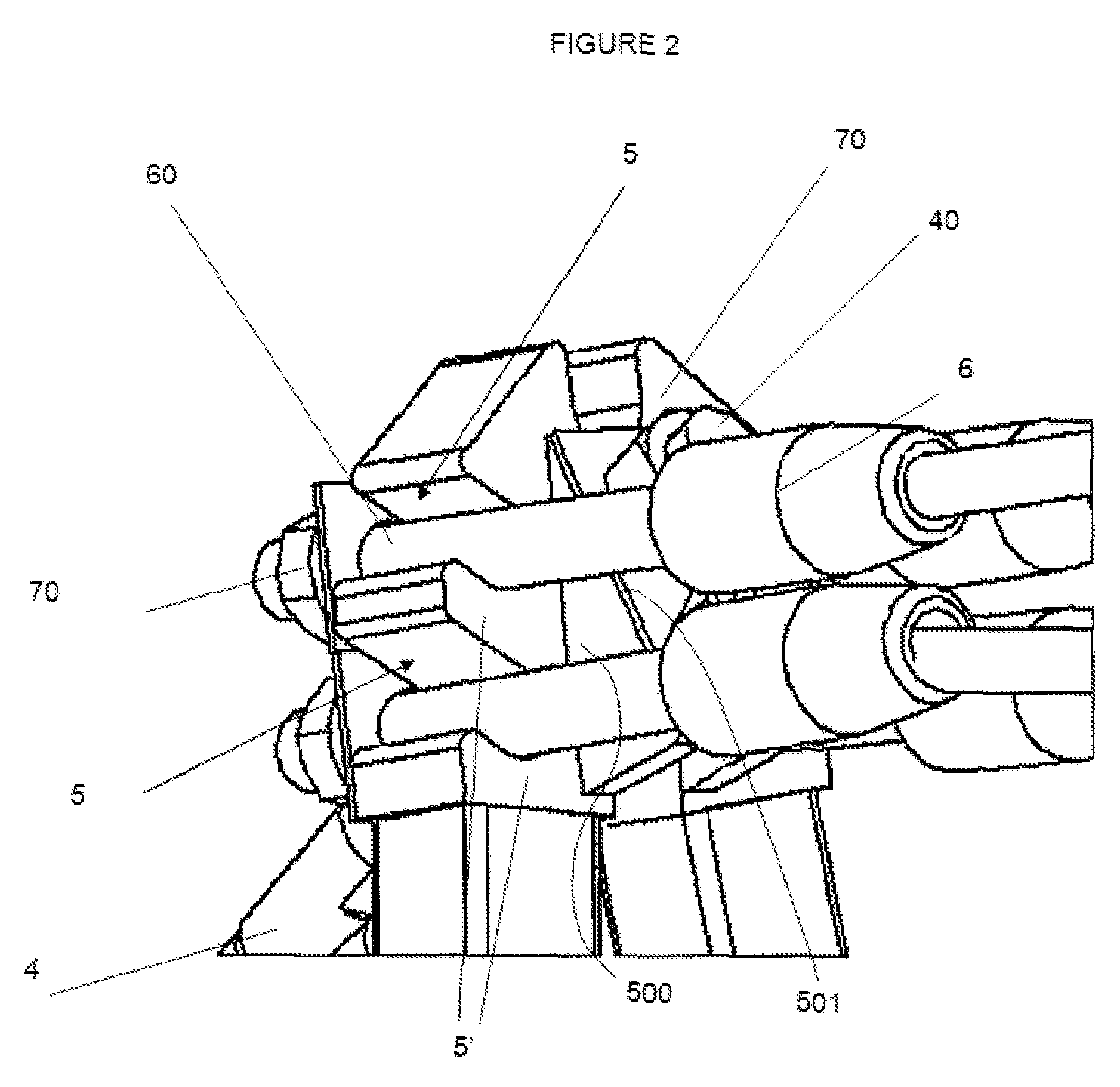
[0043]With respect to FIGS. 1-2 there is provided a terminal post (100) which has two converging uprights (1) which form a substantially inverted V-shape. The post (100) has an anchor-cable portion in the form a slot (2), located between the uprights (1) and beneath the top (3) of the post (100), in which one end of anchor cables (4) are retained. The back of the slot (2) includes, on either side, two angled walls (500) having outer edges (501). The angle that the outer edges (501) intersect the longitudinal axis of the anchor-cables is preferably an angle of around 92°. The opposite end of the anchor cables (4) are connected to one end (10) of a horizontal ground anchored member (11). The anchor cables (4) pass from post (100) to one end (9) of the member (11) which is hollow through to the other end (10). The angle of anchor cables (4) is substantially 45° or more with regard to the horizontal. This helps ensure the anchor cables (4) drop out of the slot (2) up on a head on impact...


PUM


Abstract

A terminal post for a cable barrier which is of a unitary post construction. The integrally formed post has a cable barrier portion for retaining barrier cable(s) and an anchor-cable portion for retaining anchor cable(s). The cable barrier includes at least one cable-barrier portion which, in use, receives and retains one or more barrier-cables used in the cable barrier and at least one anchor-cable portion in the form of a central groove, which, in use, receives and retains one or more anchor-cables which are anchored so as to counter balance the force applied to the terminal post by the barrier-cable(s). The cable-barrier portion(s) and the anchor-barrier portion(s) within the post body are configured so that, in use, at least one of the anchor-cable(s) and barrier-cable(s) are releasable from the body during a collision with a vehicle where the anchor-cables act as a ramp and / or snag during the collision.

Description

TECHNICAL FIELD[0001]The present invention relates to improvements in and relating to cable-barriers. In particular, though not solely, the present invention is directed towards an improved terminal post used as part of an anchoring system for cable-barriers, used on the outer edge of roads and / or vehicle road lanes requiring separation by a barrier.BACKGROUND ART[0002]The present invention will now be described in relation to cable-barriers for use in relation to roading networks. However, this should not be seen as limiting, as aspects of the present invention may also have application in relation to different fields.[0003]The applicant has previously devised an improved anchor-body and terminal post for a cable barrier which is fully described WO2007 / 129915. This improved terminal post overcomes the ramp and snag situations that can occur when a vehicle impacts the anchor cables of a cable barrier.[0004]The present invention represents a further improvement to the invention in WO...

Claims


Application Information

Patent Timeline
Patent Type & Authority Patents(United States)
IPC IPC(8): E01F15/06E01F15/14
CPCE01F15/06E01F15/145
Inventor JAMES, DALLAS, REX
Owner VALMONT HIGHWAY TECH
Why Eureka
Try Eureka