Architectural member and decorative article with display lighting

a technology of decorative articles and architectural members, applied in the field of architectural members, can solve the problems of structural weakness, present several problems, structural weakness of fabricated solid objects, etc., and achieve the effect of economic operation and energy saving

Inactive Publication Date: 2016-03-29
PANZELLA CHRIS
View PDF8 Cites 0 Cited by
  • Summary
  • Abstract
  • Description
  • Claims
  • Application Information

AI Technical Summary

Benefits of technology

[0017]It is another object of this invention to provide new and novel illuminatable fabricated architectural objects, such as paving blocks, building stones, panels, statuary, tiles, flooring, counter tops, furniture, or the like, that emit light of one or a plurality of colors from their surfaces while maintaining the strength and durability expected from comparable non-illuminating objects, concrete pavers, stepping stones, counter tops, flooring, or the like, and that can do so at relatively low cost while being attractive in appearance, versatile, functional, and durable. Such illuminatable objects to be able to be manufactured in almost any desired shape, with almost any design, or designs, in almost any desired color, where the colors, design, and light source means are light emitting diodes (LED's) positioned at the surface and may be rapidly and easily changed or replaced through the surface without the need to replace the entire object assembly, where the fabricated hard objects can be used on either hard or compressible surfaces, as desired.
[0022]It is therefore an object of this invention to provide new and novel architectural members which are illuminatable fabricated objects, such as paving blocks, building stones, panels, statuary, tiles, flooring, counter tops, or the like, that emit light of one or a plurality of colors from their surfaces by way of a light source or sources including one or more light emitting diodes (LED'S) positioned at such surface and removable and changeable through said surface and wherein the power for the illumination is provided by solar power, and where the solar-powered object maintains its durability even under harsh conditions including the damaging effects of physical and chemical weathering and heavy vehicular and pedestrian traffic, and can be offered in almost any desired design in almost any desired color.
[0023]The present invention satisfies the heretofore unmet need for self-illuminating, fabricated, solid objects, such as self-illuminating paving blocks, building stone, tiles, flooring, counter tops, or statuaries, that emit light from their surfaces, while possessing strength comparable to a non-illuminating concrete, or other suitable material, paving blocks, building stones, or cast statues, providing for inexpensive to manufacture, self-illuminating fabricated solid objects, that are attractive, versatile, functional, and adapted to include one or more patterns of various colored light and where the colors, design, and light source may be rapidly and easily changed or replaced without the need to replace the entire object, and where the fabricated hard objects are useable on either hard or compressible surfaces, as desired. Self-illuminating objects made according to the teachings of the present invention require little or no maintenance.
[0024]The present invention achieves the above and more by setting forth novel self-illuminating fabricated architectural solid objects, such as paving stones, tiles, or statuary, wherein the objects have any known, or yet to be known, light emitting diodes (LED's) disposed at a visually exposed surface of the object. The self-illuminating objects may also provide for illuminated colored patterns, seasonal designs, informational text, or advertising. A plurality of designs in various colors may exist on a single object to provide, for example, a plurality of illuminated seasonal patterns, lit in colors that are associated with the season. These durable objects have a long life. The LED's can be positioned at the surface of the object, and worn-out light sources can be replaced relatively easily and rapidly.
[0027]The electrical energy source may be powered by traditional AC electrical sources, electrical batteries, or other powering source, such as solar, wind, or chemically or organically derived energy. Usually an LED light source operates at low voltage levels requiring only low power, such as a 12 volt source, and is thus economical to run and energy efficient.

Problems solved by technology

These cavities may create a structural weakness and a place for moisture or other contaminants to collect.
These systems, however, may present several problems.
A relatively large cavity is required to house the power system and that may create a structural weakness within the fabricated solid object.
The relatively soft, transparent material used as a surface cover may create additional problems.
The soft material may not withstand the damaging effects of both physical and chemical weathering to which it is exposed, and / or to the wearing effects of the weight of objects supported thereon and / or pedestrian or vehicular traffic.
This type of system use a soft, plastic-like material placed over the light elements through which the light can emanate, but this approach suffers from the same limitations of poor durability as discussed above.
Additionally, these systems can only be used in the initial installation of a walkway or a roadway.
These lenses and prisms, however, result in glass or other transparent or translucent weak material being located on the surface of the respective and usually rather complex housings.
These are limited, though, by the fact that they must be fabricated from clear transparent materials such as methylmethacrylate, Lexan, RTM, acrylic, or the like.
These materials are inherently soft in the sense that they would not be practical for use where they would be continuously exposed to harsh weather conditions or more than occasional physical wear and tear.
These systems, however, do not provide any means for replacing a worn-out, damaged, or imperfect light source.
For these systems another disadvantage is that the paving blocks must be installed over a compressible aggregate, such as finely crushed gravel, in order to provide for the external wiring.
Although such systems may allow for the use of a variety of colored light sources, once a color for the lights in a given block is chosen, there is no way to change the color of the lights, such as from orange for Halloween celebration to red and green for a Christmas theme, without replacing the entire block.
Furthermore, such systems make no provision for a choice of design of a given block such as the choice to change from a pumpkin to a Christmas tree—again, the only choice is to change the entire block.
Self-illuminating fabricated solid objects, such as those shown and described in U.S. Pat. No. 7,131,761 patented on Nov. 7, 2006 and U.S. Pat. No. 7,204,629 patented on Apr. 17, 2007, by Pipo et all for Self-illuminating Fabricated Solid Material Objects, thus, usually present problems because they require chambers, grooves, channels, pockets or panels of significant size for housing a light bulb or other light source from which light is emitted through optical conductive material extending from the light source to openings located on the top surface of the solid block.
Additionally, none of these objects provides for an illuminated fabricated solid object, such as a paving block or stepping stone that has the strength, versatility and functionality of a concrete block or stepping stone, that provides for a lighted surface that includes various colors, patterns, or designs of light which may cover either part or the entire surface of the block or stone, where the light source means may be directly connected to the solid for example, where the light source means, the color of the light, and the design that is displayed on a visible surface can be changed or replaced easily and rapidly without having to replace the entire object.

Method used


Image

  • Architectural member and decorative article with display lighting
  • Architectural member and decorative article with display lighting
  • Architectural member and decorative article with display lighting

Examples


Embodiment Construction

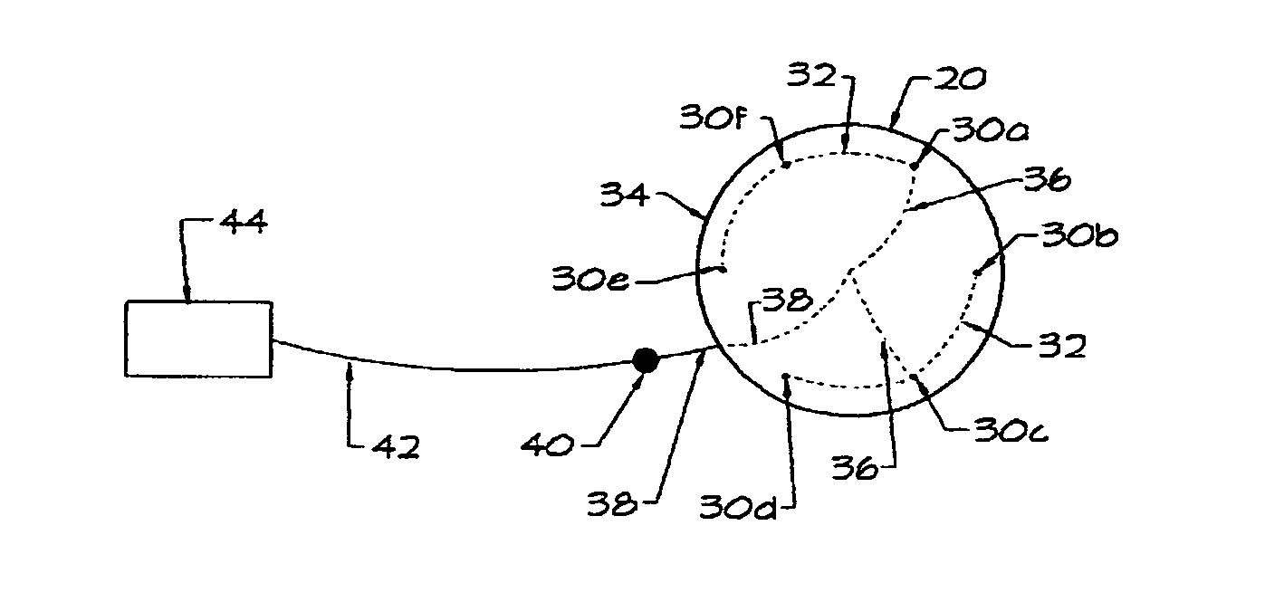
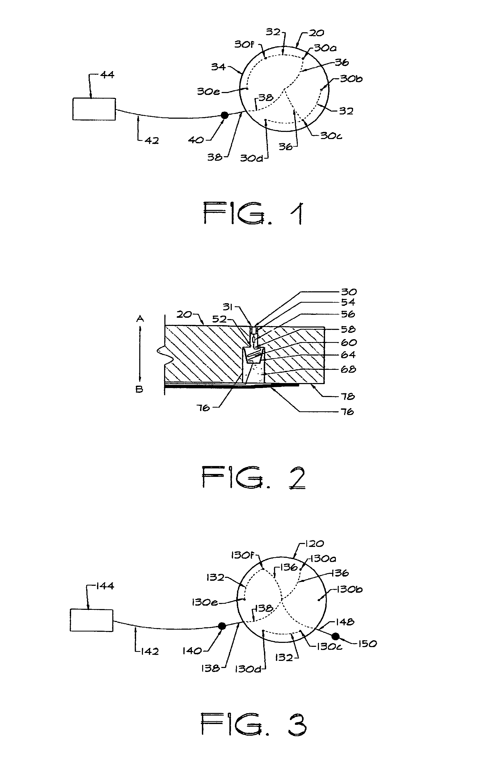
[0043]With reference to FIG. 1 there is generally shown at 20 an Arch-Mem, decorative article incorporating the instant invention, in the configuration of a patio block, paver, or an otherwise illuminating article. A selected number of LED's (light emitting diodes) 30a (FIGS. 1 & 2) through 30n (FIG. 1) are each installed into a socket 31 (FIG. 2) that are, in turn, imbedded in article 20, equi-distant apart in an imaginary circle 32 near-to but spaced from the peripheral edge 34 of article 20 so as not to affect the stability and integrity of article 20. Article 20 has been shown with six LED's 30 all emitting illumination of the same color and equally spaced around imaginary circle 32: it being understood that: more or less LED's may be so deployed; that the LEDs need not necessarily be deployed in any kind of circle but may be embedded in another pattern or not in any pattern; and that all LEDs may emit illumination of the same color or different combinations of colors; all depen...


PUM


Abstract

New and novel illuminatable fabricated decorative articles and architectural members such as paving blocks, building stones, panels, statuary, tiles, flooring, counter tops, furniture, or the like, emit or display, light of one or a plurality of colors from their surfaces by way of a light source or sources positioned at such surface and removable and changeable through said surface. More specifically architectural members, especially objects, articles, and the like used in construction, constructions, manufacturers and fabrications; and more particularly to such members that incorporate illumination and / or display lighting.

Description

BACKGROUND OF THE INVENTION[0001]1. Field of Application[0002]This invention relates to architectural members, especially objects, articles, and the like used in construction, constructions, manufacturers and fabrications; and more particularly to such members that incorporate illumination and / or display lighting.[0003]2. Description of the Prior Art[0004]The present invention relates generally to architectural members and illuminateable decorative articles that constitute illuminatable objects and more particularly to fabricated, solid, objects that have one or more viewable surfaces to be illuminated for a variety of selected purposes, and which may, when illuminated, define driveways, walkways, pathways, patios, vestibules, flooring and the like and / or display designs, greetings, or other information possibly even in a choice of colors and which for brevity may also be referred to as “Arch-Mems”.[0005]Historically, illumination or lighting, as hereinabove set out, has been mainly...

Claims


Application Information

Patent Timeline
Patent Type & Authority Patents(United States)
IPC IPC(8): F21S8/02F21V19/04G09F13/00F21S9/03F21S2/00F21V31/04E04F10/00E01F9/00F21K99/00F21V33/00F21W121/00
CPCE01F9/00E04F10/00F21K9/30F21S2/00F21S9/037F21V19/042F21V31/04F21S8/022F21V33/006G09F13/00F21W2121/00F21Y2101/02F21Y2103/022E01C17/00E04F15/02F21V19/04F21K9/20F21Y2103/33F21Y2115/10G09F19/22G09F2019/223Y02B10/10
Inventor PANZELLA, CHRIS
Owner PANZELLA CHRIS
Why Eureka
Try Eureka