Method for controlling a polyphase voltage inverter
a voltage inverter and polyphase technology, applied in the direction of dynamo-electric converter control, motor/generator/converter stopper, polyphase induction motor starter, etc., can solve the problem of large memory consumption, inability to determine the quantity of neutral to be added, and control techniques with drawbacks
- Summary
- Abstract
- Description
- Claims
- Application Information
AI Technical Summary
Benefits of technology
Problems solved by technology
Method used
Image
Examples
first embodiment
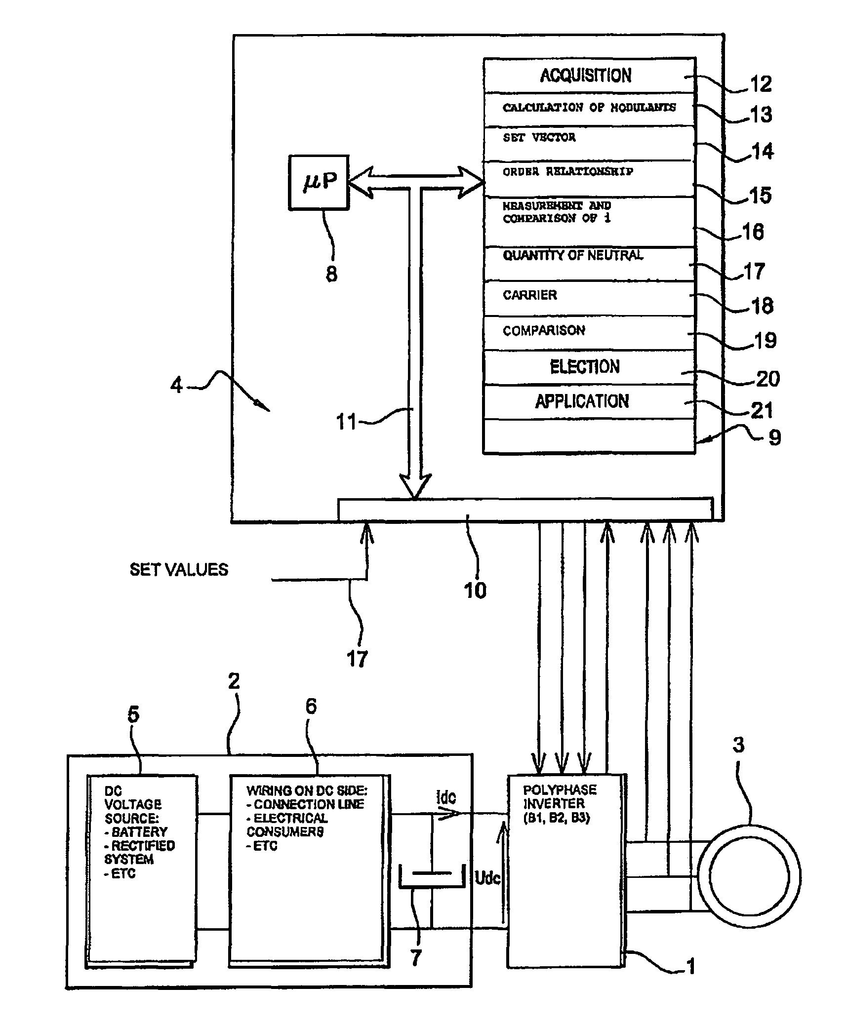
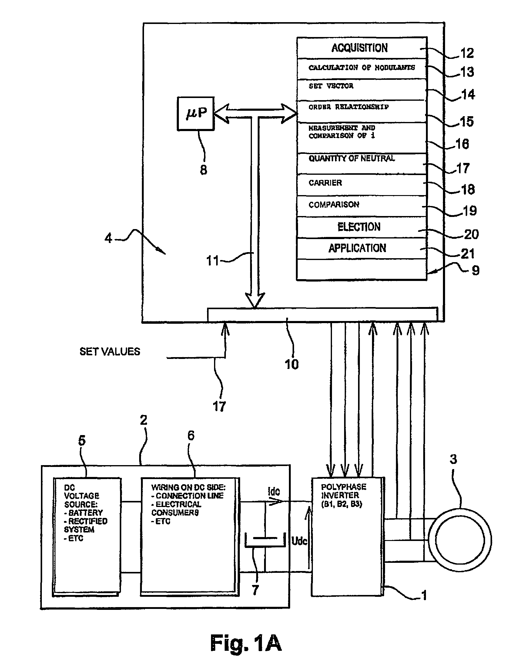
[0129]In a first embodiment, the bridge arm to be inhibited with respect to the phase currents is determined. In this case, in order to determine the bridge arm to be inhibited, the control logic 4 applies steps 40 to 45. Inhibiting a bridge arm means keeping the said bridge arm in a given state. In other words, the states of the switches of the said bridge arm remain unchanged. There is no switching of the arm.
[0130]At step 40, the control logic determines the bridge arm to be inhibited with respect to the current vector {right arrow over (i)}. The inhibiting of a bridge arm will make it possible to reduce the switching losses in the switches.
[0131]To this end, at step 41, in a first, non-limitative variant embodiment, the control logic 4 first selects two bridge arms among the three, able to be inhibited according to an order relationship between the three modulants mod1, mod2, mod3 of the three bridge arms, this order relationship being, in a non-limitative example, a comparison....
second embodiment
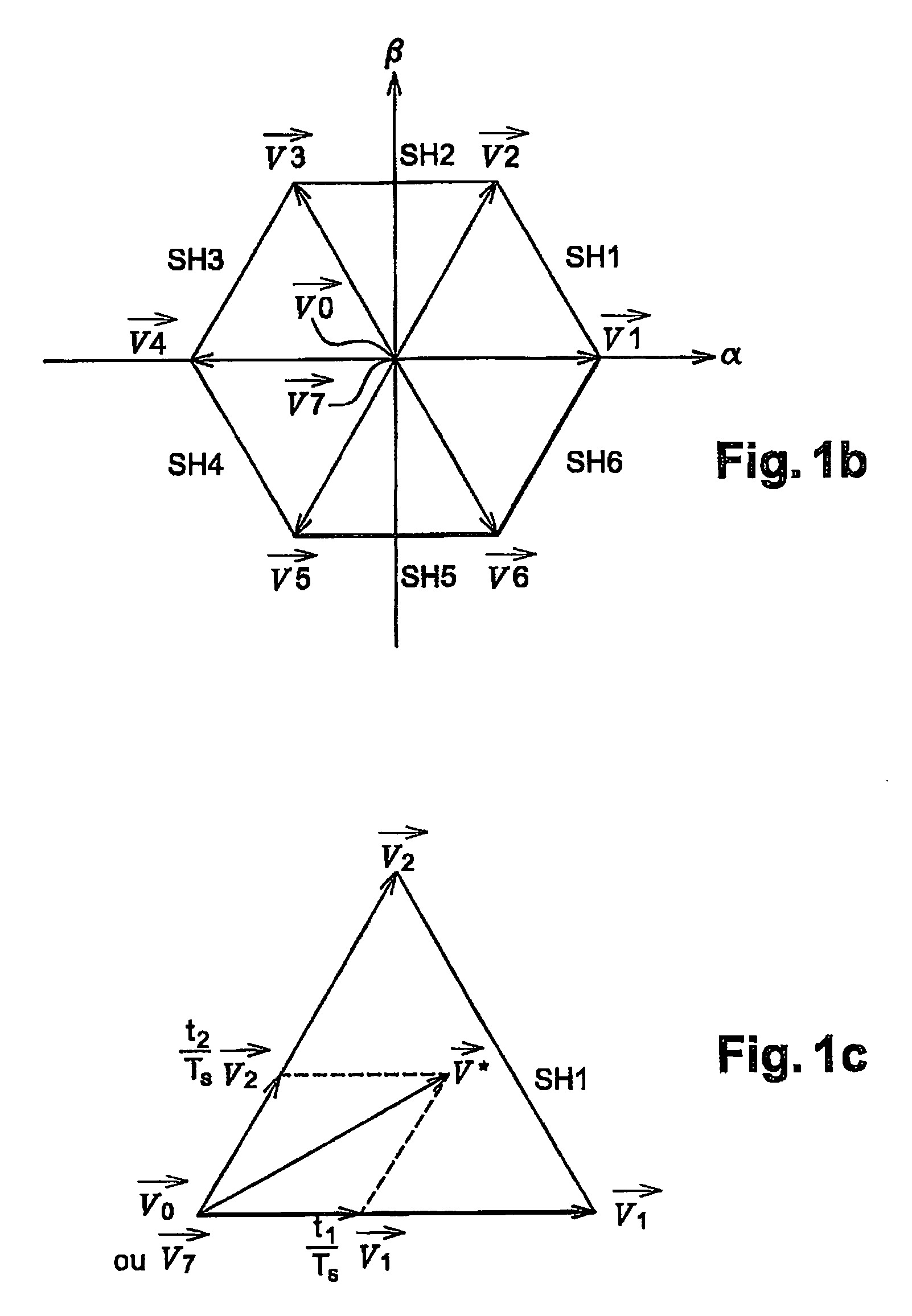
[0151]In a second embodiment, the bridge arm to be inhibited is determined with respect to the set voltage vector {right arrow over (V*)} and more particularly the sectorial position of the set voltage vector in one of the angular sectors SA of the stator reference frame. In this case, to determine the bridge arm to be inhibited, the control logic 4 applies steps 50 to 55.
[0152]In this case, the stator reference frame is subdivided into angular sectors SA illustrated in FIG. 3. Each angular sector has its vertex at the centre of the stator reference frame and forms an angle of 60°. Each of the active control vectors cuts each of the angular sectors into two equal parts. The stator reference frame comprises six angular sectors SA. The first angular sector SA1 is cut into two equal parts by the control vector {right arrow over (V1)} and so on up to the sixth angular sector SA6, which is cut by the control vector {right arrow over (V6)}.
[0153]At step 50, the control logic 4 determines ...
PUM
 Abstract
Description
Claims
Application Information
 - R&D
- Intellectual Property
- Life Sciences
- Materials
- Tech Scout
- Unparalleled Data Quality
- Higher Quality Content
- 60% Fewer Hallucinations
Browse by: Latest US Patents, China's latest patents, Technical Efficacy Thesaurus, Application Domain, Technology Topic, Popular Technical Reports.
© 2025 PatSnap. All rights reserved.Legal|Privacy policy|Modern Slavery Act Transparency Statement|Sitemap|About US| Contact US: help@patsnap.com


