Multi-sensor touch integrated display driver configuration for capacitive sensing devices

a capacitive sensing device and integrated display technology, applied in the direction of instruments, computing, electric digital data processing, etc., can solve the problems of increasing the number of traces that need to be routed to the controlling electronics within increasing the piece part and manufacturing cost of the touch sensing device, and increasing the number of traces that need to be routed to the controlling electronics. , to achieve the effect of reducing the effect of electrical interference, reducing signal routing complexity, and reducing electromagnetic interferen

Active Publication Date: 2016-03-29
SYNAPTICS INC
View PDF18 Cites 4 Cited by
  • Summary
  • Abstract
  • Description
  • Claims
  • Application Information

AI Technical Summary

Benefits of technology

[0010]Embodiments of the disclosure generally provide an integrated control system having an integrated controller that is configured to provide both display updating signals to a display device and a capacitive sensing signal to a sensor electrode that is disposed within the input device. The internal and / or external signal routing configurations described herein can be adapted to reduce signal routing complexity typically found in conventional devices and reduce the effect of electrical interference created by the capacitive coupling formed between the display routing, capacitive sensing routing and / or other components within the integrated control system. Embodiments can also be used to reduce electromagnetic interference (EMI) on the display and touch sensing signals received, transmitted and processed within the integrated control system.

Problems solved by technology

However, with the advent of new touch sensing technologies that include the use of absolute and transcapacitive sensing techniques, the number of sensor electrodes required to perform the touch sensing process has greatly increased, which has also greatly increased the number of traces that need to be routed to the controlling electronics within the touch sensing device.
Due to the large number of routing traces required for the absolute and / or transcapacitive sensing techniques, the borders of the display need to become excessively large.
Alternately, in some cases manufactures will resort to separating the display updating circuitry and the capacitive sensing circuitry into separate IC chips, which greatly increases the piece part and manufacturing cost of the touch sensing device.

Method used


Image

  • Multi-sensor touch integrated display driver configuration for capacitive sensing devices
  • Multi-sensor touch integrated display driver configuration for capacitive sensing devices
  • Multi-sensor touch integrated display driver configuration for capacitive sensing devices

Examples


Embodiment Construction

[0030]The following detailed description is merely exemplary in nature and is not intended to limit the invention or the application and uses of the invention. Furthermore, there is no intention to be bound by any expressed or implied theory presented in the preceding technical field, background, brief summary or the following detailed description.

General Overview

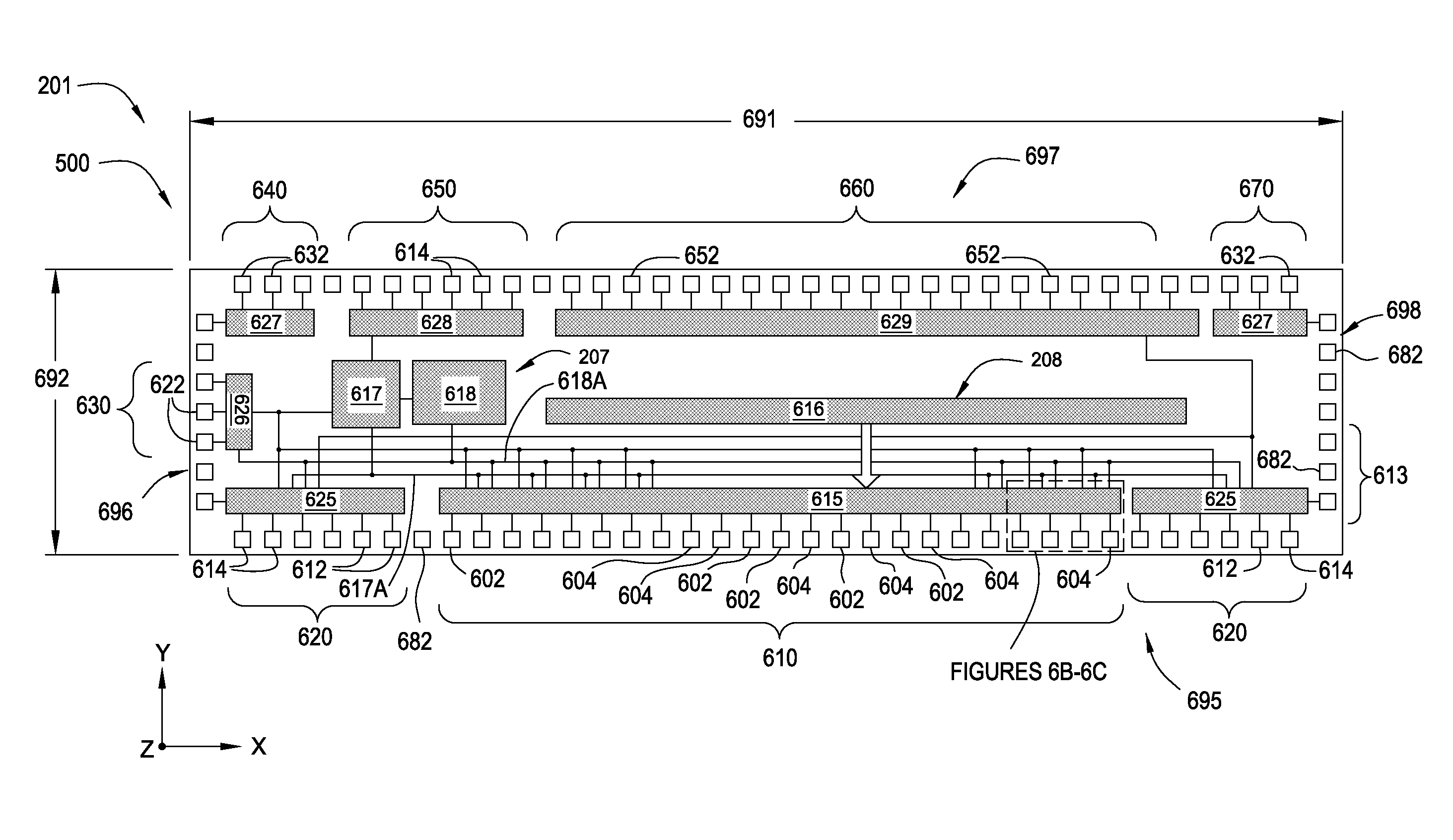
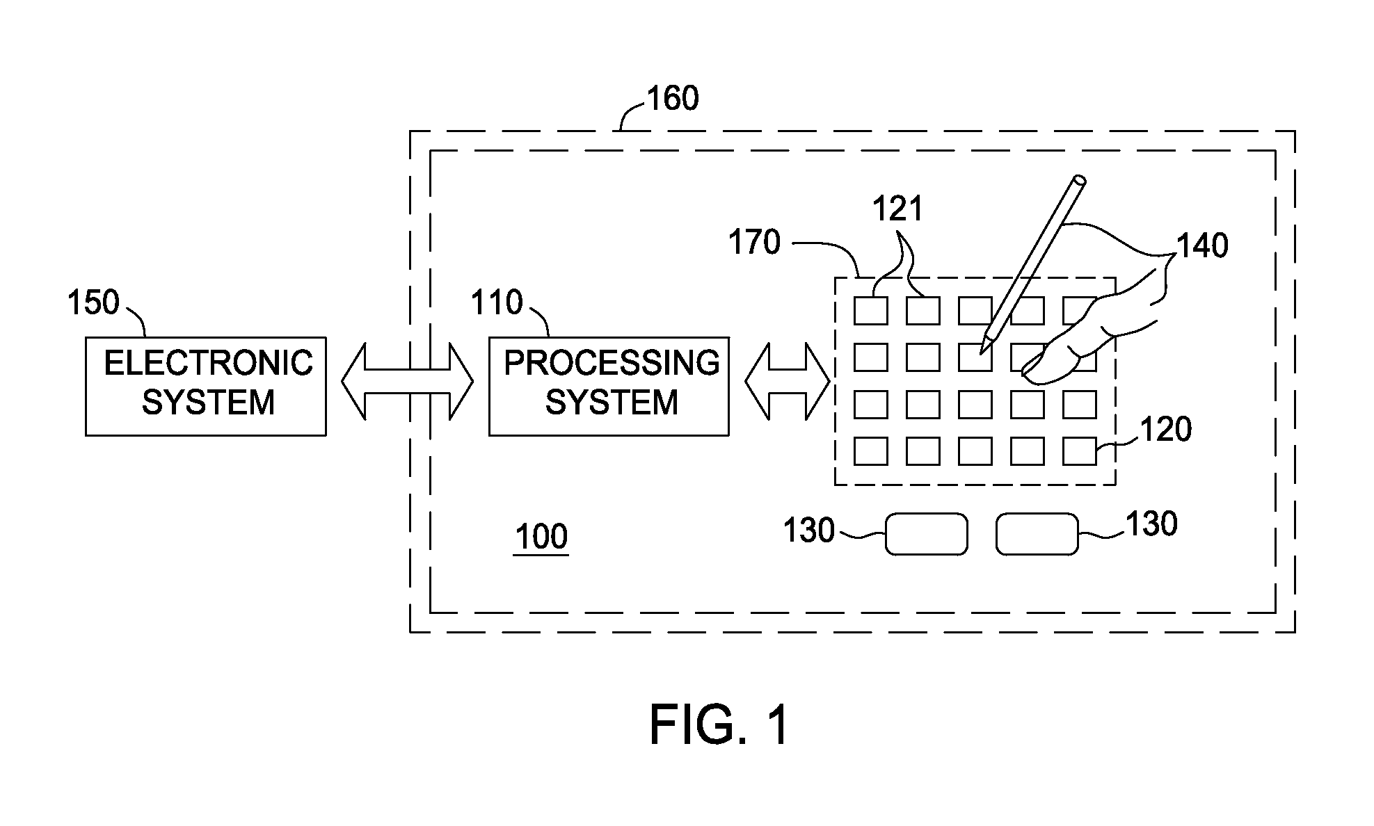
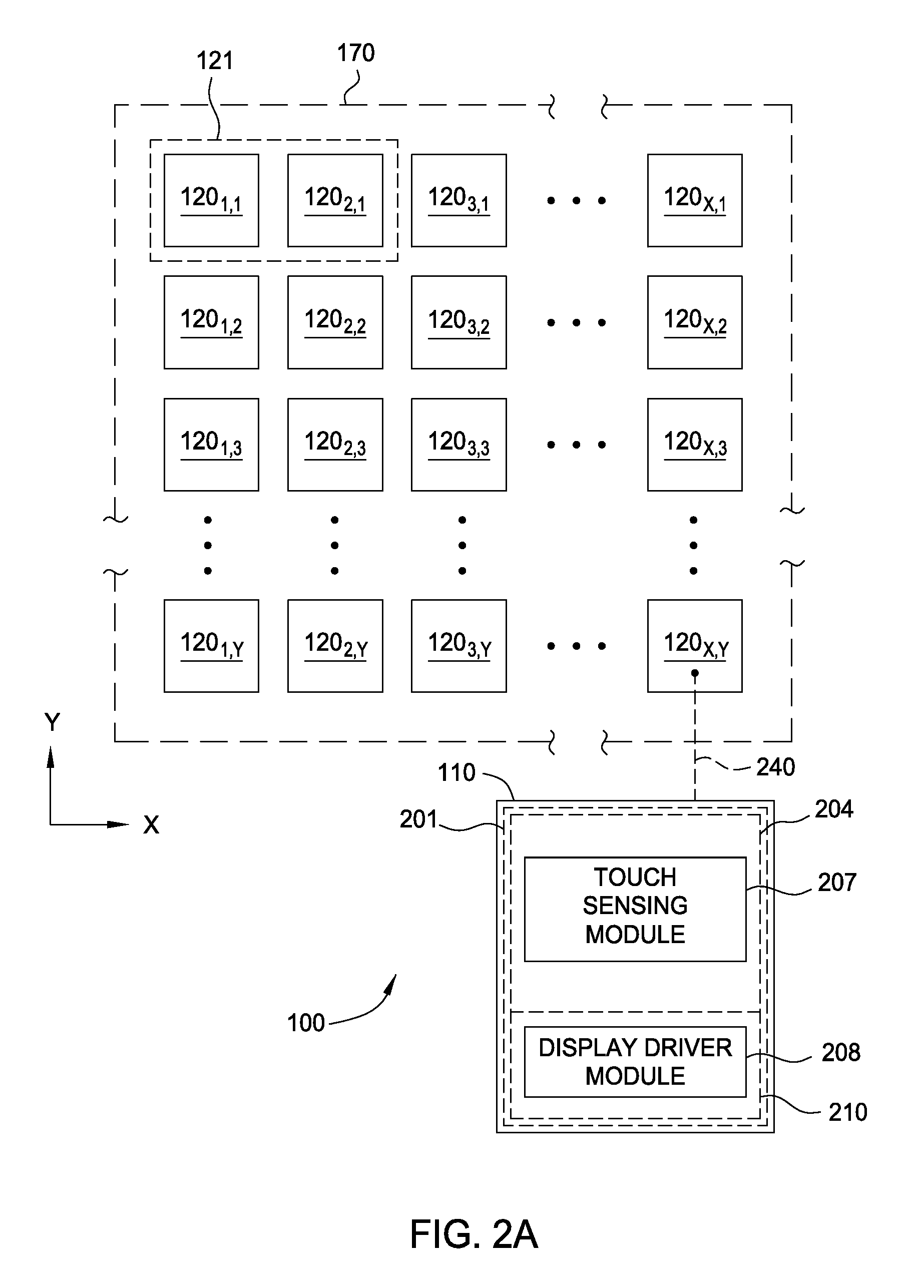
[0031]Embodiments of the disclosure provided herein generally provide an integrated control system having an integrated controller that is configured to provide both display updating signals to display electrodes disposed within a display pixel within a display device and a capacitive sensing signal to a sensor electrode that is disposed within an input device. The integrated control system is generally configured to work with a variety of integrated capacitive sensing and display applications, for example, in-cell display device configurations, on-cell display device configurations or any other similar display device confi...


PUM


Abstract

Embodiments of the disclosure generally provide an integrated control system having an integrated controller that is configured to provide both display updating signals to a display device and a capacitive sensing signal to a sensor electrode that is disposed within the integrated input device. The internal and / or external signal routing configurations described herein can be adapted to reduce signal routing complexity typically found in conventional devices and reduce the effect of electrical interference created by the capacitive coupling formed between the display routing, capacitive sensing routing and / or other components within the integrated control system. Embodiments can also be used to reduce electromagnetic interference (EMI) on the display and touch sensing signals received, transmitted and processed within the integrated control system.

Description

CROSS-REFERENCE TO RELATED APPLICATIONS[0001]This application claims benefit of U.S. provisional patent application Ser. No. 61 / 885,999, filed Oct. 2, 2013, which is hereby incorporated herein by reference.BACKGROUND OF THE INVENTION[0002]1. Field of the Invention[0003]Embodiments of the present invention generally relate to a system and method for sensing a position of an input object over a sensing region of a proximity sensing device.[0004]2. Description of the Related Art[0005]Input devices including proximity sensor devices, also commonly called touchpads or touch sensor devices, are widely used in a variety of electronic systems. A proximity sensor device typically includes a sensing region in which the proximity sensor device determines the presence, location and / or motion of one or more input objects, such as a finger. Proximity sensor devices may be used to provide interfaces for an electronic system. For example, proximity sensor devices are often used as input devices for...

Claims


Application Information

Patent Timeline
Patent Type & Authority Patents(United States)
IPC IPC(8): G09G5/00G06F3/041G06F3/044
CPCG06F3/0412G06F3/044G09G5/00G09G3/20G09G2300/0426G09G2310/0275G09G2330/06G06F3/0443G06F3/0416G02F1/13338H10K59/40
Inventor LUDDEN, CHRISTOPHER, A.
Owner SYNAPTICS INC
Why Eureka
Try Eureka