Reducing audio distortion in an audio system

a technology of audio system and audio distortion, applied in the field of audio system, can solve the problems of loss of acoustical fidelity is especially pronounced with small loudspeakers, non-flat frequency response of coils, etc., and achieve the effect of increasing audio fidelity and measuring the capacitance of loudspeakers

Active Publication Date: 2016-03-29
QUANTANCE
View PDF8 Cites 0 Cited by
  • Summary
  • Abstract
  • Description
  • Claims
  • Application Information

AI Technical Summary

Benefits of technology

[0007]Embodiments disclosed herein describe an audio system that measures a test current through the loudspeaker as a way to measure the capacitance of the loudspeaker. The test current is used as feedback to generate a feedback signal that represents an actual displacement of the loudspeaker diaphragm. The feedback signal can then be used in a feedback loop to adjust a target audio signal, resulting in increased audio fidelity.

Problems solved by technology

However, in a real loudspeaker, the movement of the diaphragm is not exactly proportional to the applied electrical signal, and this deviation leads to loss of acoustical fidelity.
The loss of acoustical fidelity is especially pronounced with small loudspeakers, such as those found in mobile phones, tablet computers, laptops, and other portable devices.
This results in a non-flat frequency response of the coil.
Second, the effect of the magnetic field of the magnet on the coil is not constant as the position of the coil changes inside the magnet.
Third, the springiness of the suspension supporting the diaphragm is not constant, and varies depending on how far it the diaphragm is displaced from its nominal position.
All of these factors lead to increased distortion in the sound produced by a loudspeaker.

Method used


Image

  • Reducing audio distortion in an audio system
  • Reducing audio distortion in an audio system
  • Reducing audio distortion in an audio system

Examples


Embodiment Construction

[0022]The Figures (FIG.) and the following description relate to various embodiments by way of illustration only. It should be noted that from the following discussion, alternative embodiments of the structures and methods disclosed herein will be readily recognized as viable alternatives that may be employed without departing from the principles discussed herein.

[0023]Reference will now be made in detail to several embodiments, examples of which are illustrated in the accompanying figures. It is noted that wherever practicable similar or like reference numbers may be used in the figures and may indicate similar or like functionality. The figures depict various embodiments for purposes of illustration only. One skilled in the art will readily recognize from the following description that alternative embodiments of the structures and methods illustrated herein may be employed without departing from the principles described herein.

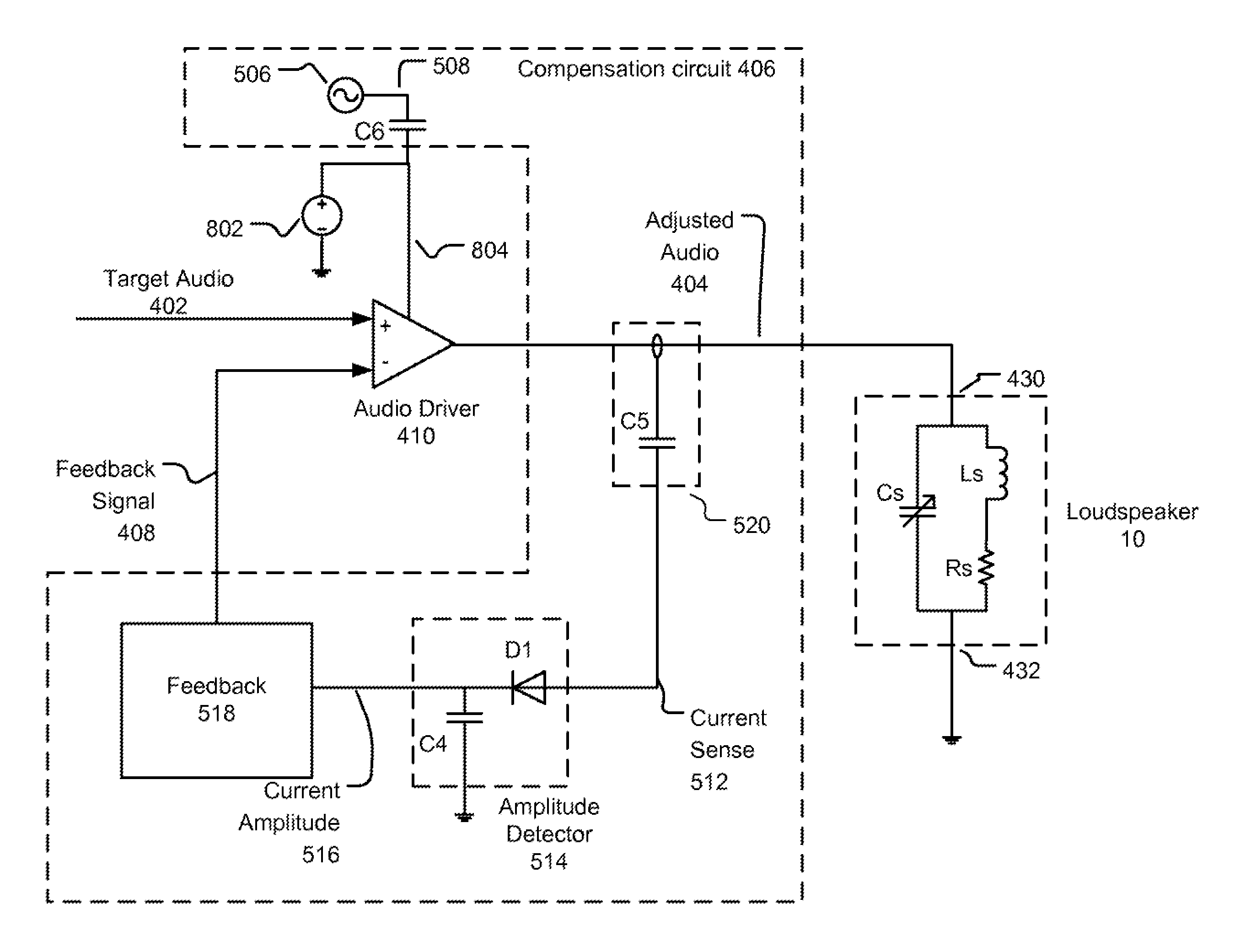
[0024]Embodiments disclosed herein describe an audio s...


PUM


Abstract

An audio system comprises an audio driver configured to receive a target audio signal and a feedback signal and to generate an adjusted audio signal responsive to the target audio signal and the feedback signal. A loudspeaker is configured to convert the adjusted audio signal into acoustical sound. A test signal generator is configured to generate a test signal having a higher frequency than the target audio signal. The test signal causes a test current to flow through the loudspeaker. A current sensing circuit is configured to measure the test current flowing through the loudspeaker and to generate a current sense signal indicative of the test current. A feedback circuit is configured generates the feedback signal responsive to the current sense signal.

Description

BACKGROUND[0001]1. Field of Technology[0002]Embodiments disclosed herein relate to audio systems, and more specifically to an audio system for reducing audio distortion of a loudspeaker.[0003]2. Description of the Related Arts[0004]A loudspeaker is a device that receives an electrical signal and converts the electrical signal to audible sound. Loudspeakers can include a voice coil that is inside of a magnet and is also attached to a diaphragm (e.g., a cone). When an electrical signal is applied to the voice coil, the coil generates a magnetic field that causes the voice coil and its attached diaphragm to move. The movement of the diaphragm pushes the surrounding air and generates sound waves.[0005]For better sound fidelity, the sound waves produced by a loudspeaker should be proportional to the electrical signal applied to the loudspeaker. However, in a real loudspeaker, the movement of the diaphragm is not exactly proportional to the applied electrical signal, and this deviation le...

Claims


Application Information

Patent Timeline
Patent Type & Authority Patents(United States)
IPC IPC(8): H04R29/00H03G11/00H04R3/04H04R3/00
CPCH04R29/001H04R3/04H04R3/002H04R3/08H04R29/003
Inventor VINAYAK, VIKAS
Owner QUANTANCE
Why Eureka
Try Eureka