
Metal strain relief device for use in an optical communications system, an optical fiber cable that employs the strain relief device, and a method

a technology of optical communication system and strain relief device, which is applied in the direction of optical light guide, fibre mechanical structure, instruments, etc., can solve the problems of limited ability to increase bandwidth by increasing the size of the array, inability to z-plugging parallel optical transceiver modules b>6/b>, and large space on the front panel, etc., to achieve the effect of desired flexibility and desired stiffness

Active Publication Date: 2016-04-05
AVAGO TECH INT SALES PTE LTD
View PDF48 Cites 1 Cited by
  • Summary
  • Abstract
  • Description
  • Claims
  • Application Information

AI Technical Summary

Benefits of technology

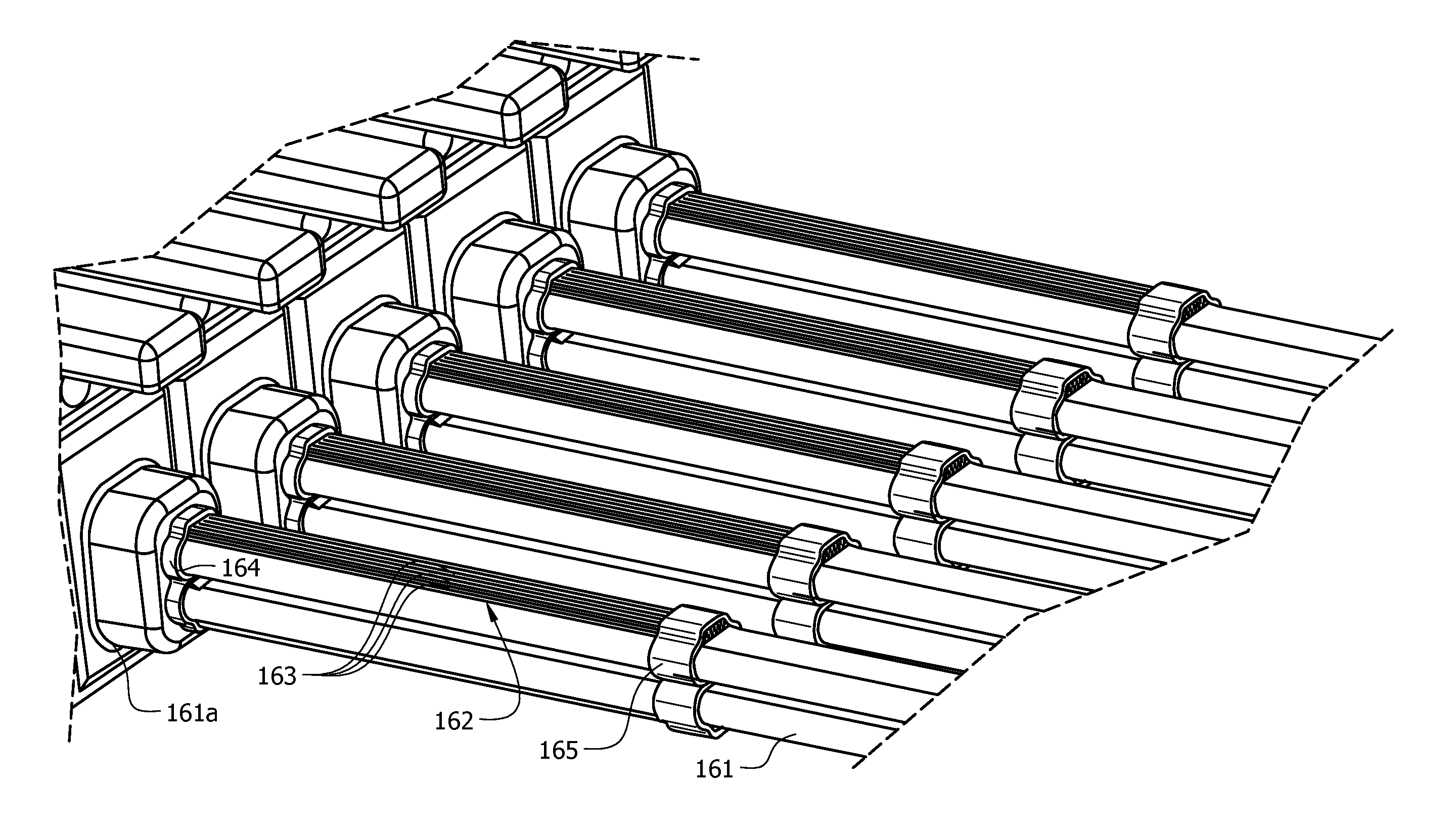
[0011]The invention is directed to a strain relief device for use with an optical fiber cable of an optical communications system, an optical fiber cable equipped with the strain relief device, and a method. The strain relief device comprises a plurality of metal wires, or rods, grouped into a bundle of parallel metal wires and a clamping mechanism for clamping first and second ends of the metal wires to an optical fiber cable. The clamped bundle of metal wires forms a spring having a spring constant that provides it with a desired stiffness and a desired flexibility.

Problems solved by technology

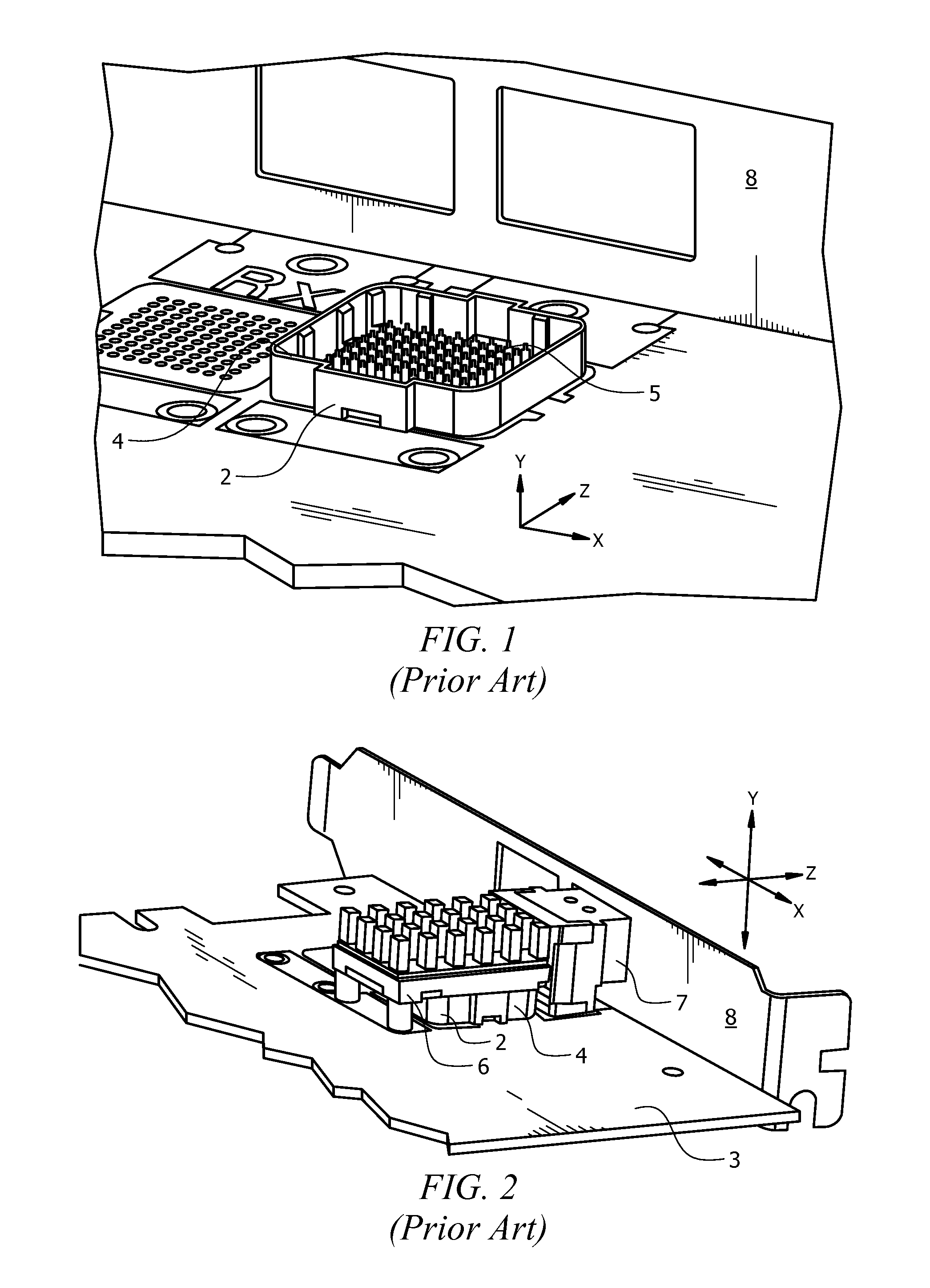
There are, however, disadvantages associated with edge-mounted arrangements of the type shown in FIG. 2.
One such disadvantage is that the receptacles 7 and the respective optical connector modules (not shown) are relatively wide in the X-dimension and therefore consume large amounts of space on the front panel 8.
Because space on the front panel 8 is limited, the ability to increase bandwidth by increasing the size of the array is also limited.
Another disadvantage associated with the edge-mounted arrangement shown in FIG. 2 is that the parallel optical transceiver modules 6 are not Z-pluggable, i.e., they cannot be plugged into and unplugged from the front panel 8.
This makes the tasks of installing the modules 6 and swapping the modules 6 out relatively difficult and time-consuming.

Method used


Image

  • Metal strain relief device for use in an optical communications system, an optical fiber cable that employs the strain relief device, and a method
  • Metal strain relief device for use in an optical communications system, an optical fiber cable that employs the strain relief device, and a method
  • Metal strain relief device for use in an optical communications system, an optical fiber cable that employs the strain relief device, and a method

Examples


Embodiment Construction

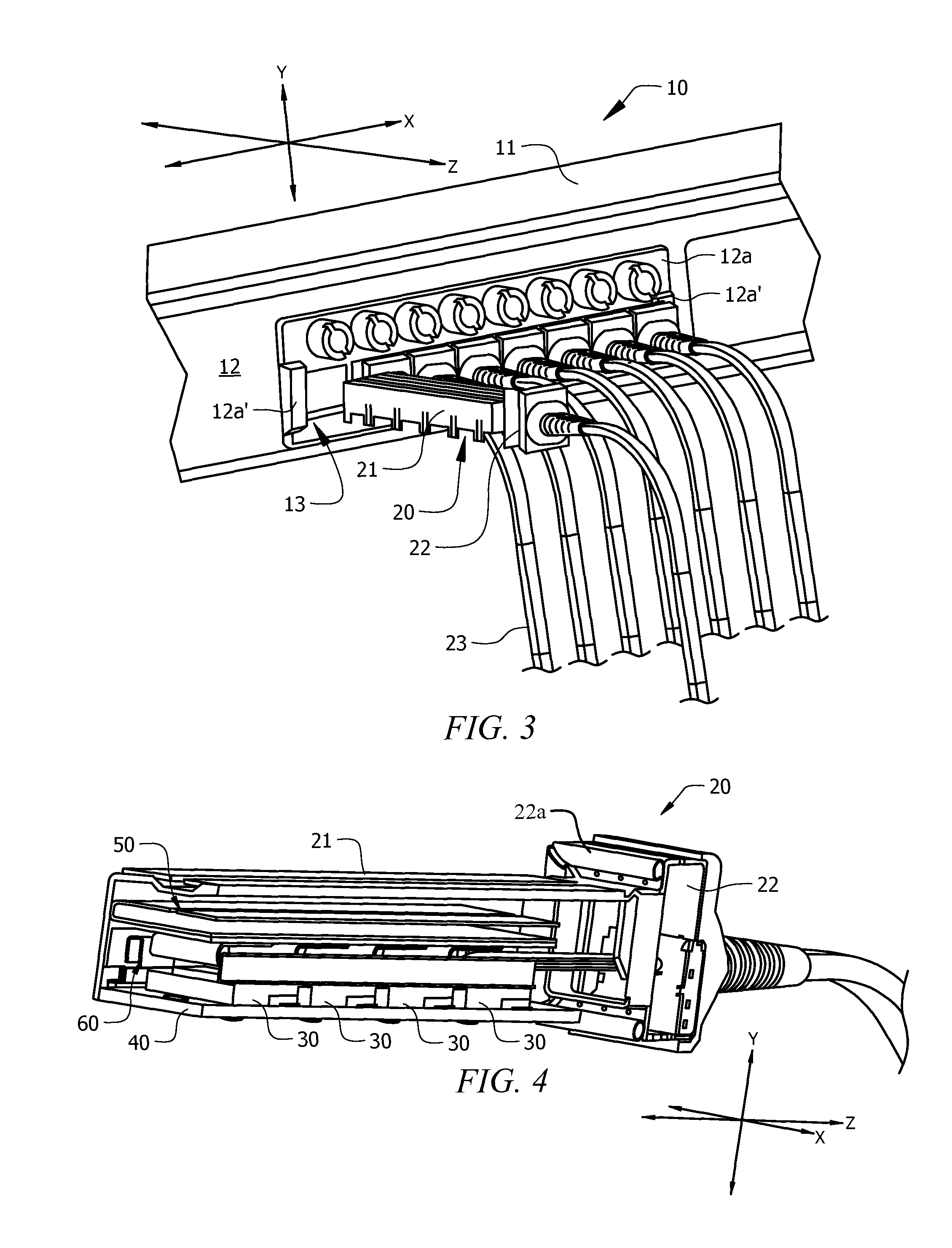
[0030]In accordance with the invention, a strain relief device is provided for use in an optical communications system. For illustrative purposes, the strain relief device and method will be described with reference to a Z-pluggable optical communications module (OCM) with which the strain relief device may advantageously be used. The strain relief device, however, is not limited to being used with any particular type of optical communications module.

[0031]The Z-pluggable OCM contains multiple parallel OCMs (POCMs) and is configured to be removably plugged into an opening formed in a front panel of an optical communications system. When the Z-pluggable OCM is plugged in a forward Z-direction into the opening formed in the front panel, an actuator mechanism imparts motion to the Z-pluggable OCM in the downward Y-direction to cause the Z-pluggable OCM to be mounted on an upper surface of a motherboard PCB. In order to unplug the Z-pluggable OCM, the actuator mechanism imparts motion t...


PUM


Abstract

A strain relief device and method are provided for use with an optical fiber cable of an optical communications system. The strain relief device comprises a plurality of metal wires, or rods, grouped into a bundle of parallel metal wires and a clamping mechanism for clamping first and second ends of the metal wires to an optical fiber cable. The clamped bundle of metal wires forms a spring having a spring constant that provides it with a desired stiffness and a desired flexibility.

Description

CROSS-REFERENCE TO RELATED APPLICATIONS[0001]This application is a continuation-in part of application Ser. No. 13 / 543,930, filed on Jul. 9, 2012, entitled “A Z-PLUGGABLE OPTICAL COMMUNICATIONS MODULE, AN OPTICAL COMMUNICATIONS SYSTEM, AND A METHOD,” which is incorporated herein by reference in its entirety.TECHNICAL FIELD OF THE INVENTION[0002]The invention relates to optical communications systems. More particularly, the invention relates to a metal strain relief device and a method for use in an optical communications module.BACKGROUND OF THE INVENTION[0003]A parallel optical communications module is a module having multiple transmit (TX) channels, multiple receive (RX) channels, or both. A parallel optical transceiver module is an optical communications module that has multiple TX channels and multiple RX channels in TX and RX portions, respectively, of the transceiver module. The TX portion comprises components for transmitting data in the form of modulated optical signals over...

Claims


Application Information

Patent Timeline
Patent Type & Authority Patents(United States)
IPC IPC(8): G02B6/00G02B6/44G02B6/42
CPCG02B6/44G02B6/4246G02B6/4261G02B6/4269G02B6/4292G02B6/4471
Inventor MCCOLLOCH, LAURENCE R.
Owner AVAGO TECH INT SALES PTE LTD
Learn More