
Pneumatic tire

a technology of pneumatic tires and aprons, which is applied in the direction of tire beads, rolling resistance optimization, vehicle components, etc., can solve the problems of reducing the weight and rolling resistance due to the use of small apex, and achieve the effect of reducing weight and rolling resistan

Active Publication Date: 2020-01-23
SUMITOMO RUBBER IND LTD
View PDF3 Cites 2 Cited by
  • Summary
  • Abstract
  • Description
  • Claims
  • Application Information

AI Technical Summary

Benefits of technology

The present invention is about a design for a pneumatic tire that reduces weight and rolling resistance while maintaining desired stiffness. The design includes a specific shape of the main body portion of the tire from the boundary between the tread and sidewall to the outer end of each apex. This specific shape helps to ensure the desired stiffness and reduce the amount of weight and rolling resistance in the tire. Overall, this design helps to create a tire that is both lightweight and comfortable to ride.

Problems solved by technology

However, in this case, the effect of reducing the weight and the rolling resistance due to use of the small apex diminishes.

Method used


Image

  • Pneumatic tire
  • Pneumatic tire

Examples


example 1

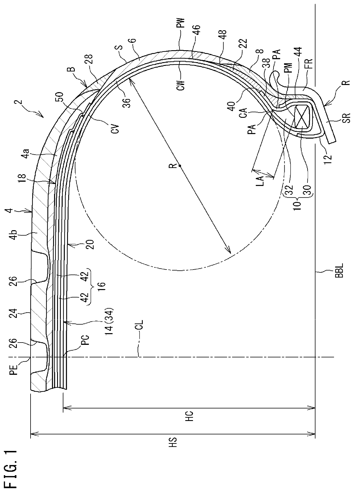
[0096]A passenger car pneumatic tire (tire size=205 / 55R16) having the basic structure shown in FIG. 1 and having the specifications shown in Table 1 below was obtained.

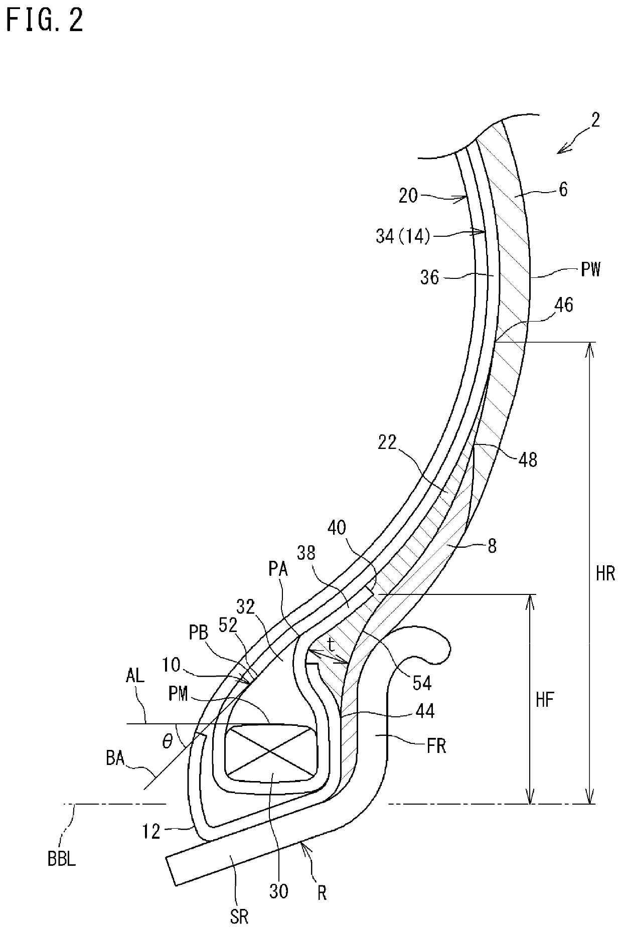
[0097]In Example 1, the ratio (R / HC) of the diameter R of the circular arc, which represents the shape of each main body portion, relative to the cross-sectional height HC of the carcass was 80%. The length LA of each apex was 10 mm. The ratio (HR / HS) of the distance HR in the radial direction from the bead base line to the outer end of each rubber reinforcing layer relative to the cross-sectional height HS of the tire was 40%. The maximum thickness t of the rubber reinforcing layer was 3 mm. The distance HF in the radial direction from the bead base line to the end of each turned-up portion was 25 mm. The fineness of each carcass cord was 1100 dtex.

[0098]In Example 1, the loss tangent LTa of the apex was 0.15, and the complex elastic modulus E*a of the apex was 100 MPa. The loss tangent LTc of each clinch was 0.05, a...

examples 4 to 6

[0101]Tires of Examples 4 to 6 were obtained in the same manner as Example 1, except that the complex elastic modulus E*r of the apex was set as shown in Table 2 below.

example 7

[0102]A tire of Example 7 was obtained in the same manner as Example 1, except that the loss tangent LTa of the apex was set as shown in Table 2 below.


PUM


Abstract

In a tire 2, a length from a center in an axial direction of a boundary between a core 30 and an apex 32 of each bead 10 to an outer end PA of the apex 32 is not less than 10 mm and not greater than 15 mm In a state where the tire 2 is mounted on a normal rim and an internal pressure of the tire 2 is adjusted to a normal internal pressure, a shape of a main body portion 36, of a carcass ply 34, which is located in a zone from a boundary portion between a tread 4 and each sidewall 6 to the outer end PA of each apex 32 is represented by a single circular arc, and a diameter of the circular arc is not less than 75% and not greater than 90% of a cross-sectional height of a carcass 14.

Description

[0001]The present application is based upon and claims the benefit of priority to Japanese Patent Application No. 2018-137730, filed Jul. 23, 2018, the entire contents of which are incorporated herein by reference.BACKGROUND OF THE INVENTIONField of the Invention[0002]The present invention relates to pneumatic tires.Description of the Related Art[0003]Each bead of a tire includes a core and an apex. A hard crosslinked rubber is used for the apex. To ensure desired stiffness, an apex having a length of about 30 mm to 40 mm is generally used.[0004]From consideration for the environment, reduction of weight and reduction of rolling resistance are required for tires. Therefore, use of a small apex having a length of about 5 mm to 15 mm is considered.[0005]For example, Japanese Laid-Open Patent Publication No. 2017-030620 discloses a bead including a first apex and a second apex located axially outward of the first apex. The first apex is the above-described small apex. The second apex i...

Claims


Application Information

Patent Timeline
Patent Type & Authority Applications(United States)
IPC IPC(8): B60C15/06B60C15/00B60C3/04
CPCB60C2015/0621B60C2015/0614B60C2015/061B60C3/04B60C15/0027B60C15/0607B60C9/02B60C15/0009B60C15/06B60C9/0292B60C15/0603B60C2015/0617Y02T10/86B60C15/0054B60C2015/009
Inventor SUENO, JUNYAHAYAMA, KOHEI
Owner SUMITOMO RUBBER IND LTD
Learn More