
Front floor panel

a technology for front and rear floor panels, applied in roofs, transportation and packaging, vehicle arrangements, etc., can solve the problems of increasing stiffness anisotropy toward the end portions at the front and rear of the floor panels, and inevitably increasing manufacturing costs, etc., and achieve the effect of desired stiffness

Active Publication Date: 2014-12-18
NIPPON STEEL CORP
View PDF2 Cites 3 Cited by
  • Summary
  • Abstract
  • Description
  • Claims
  • Application Information

AI Technical Summary

Benefits of technology

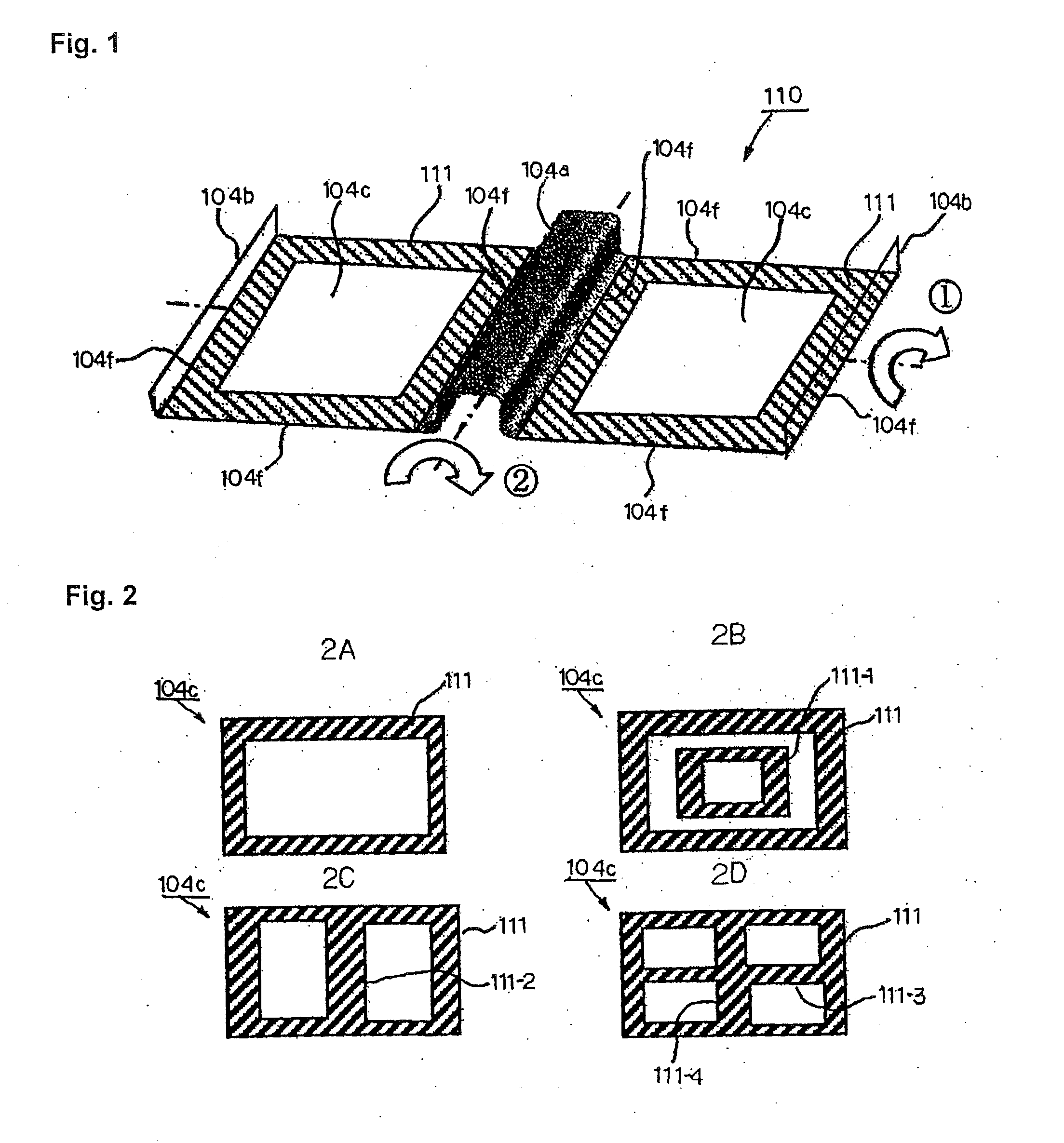
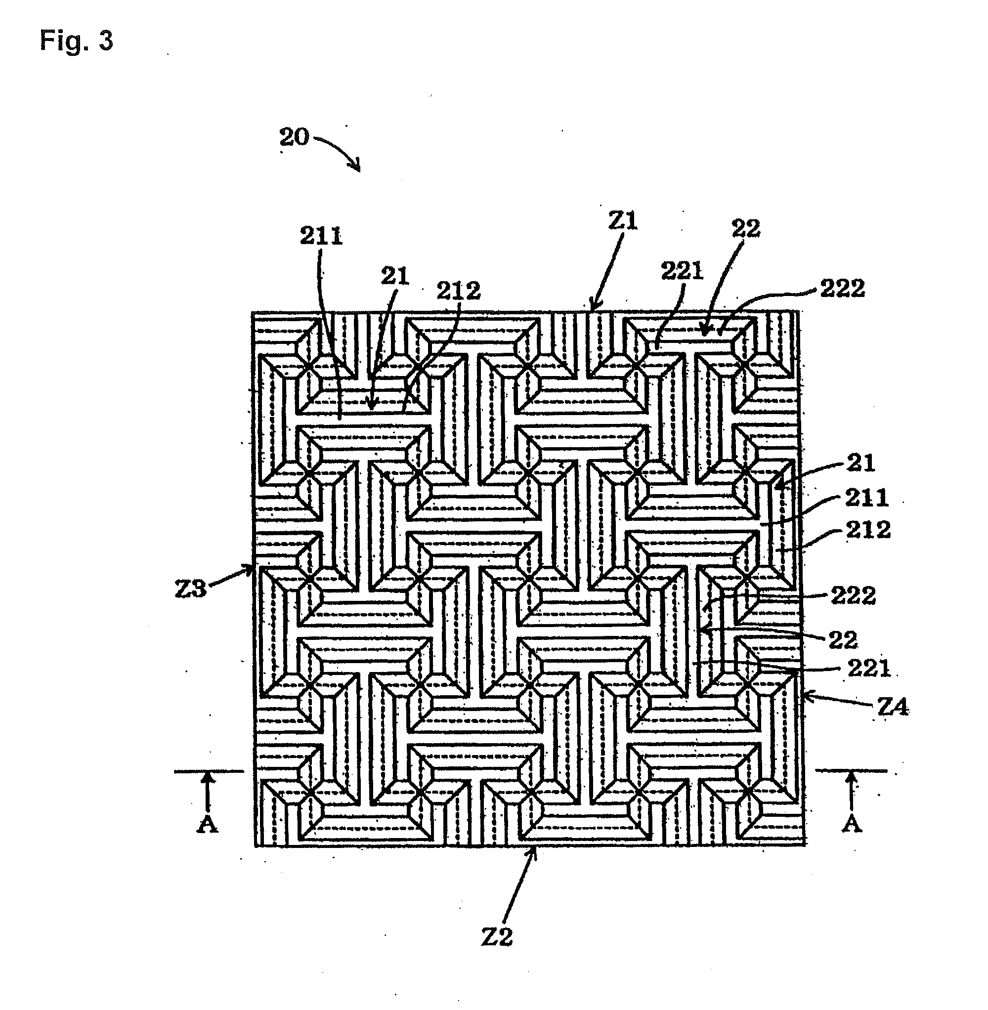
The present invention provides a front floor panel with an improved structure that increases stiffness by a plurality of unit areas being arranged in a loop-shaped convex-concave part. The minimum convex-concave part exhibits this advantage by having two or more rows of the areas each having the substantially I shape. The front floor panel made of steel has a high stiffness even at a thin sheet thickness of approximately 0.55 mm, and can be efficiently manufactured. The convex-concave part prevents excessive forming load and ensures desired stiffness and noise and vibration characteristics.

Problems solved by technology

However, according to the research of the present inventors, the advantageous effect of increasing stiffness to such an extent that can reduce the sheet thickness of a floor panel cannot be obtained by using the technology disclosed in Patent Document 1, the manufacturing cost inevitably increases since a number of convex portions are formed in the sheet material by using the technology disclosed in Patent Document 2, and further, the technology disclosed in Patent Document 3 has the problem of an increase in stiffness anisotropy toward the end portions at the front and the rear of the floor panel.

Method used


Image

  • Front floor panel
  • Front floor panel
  • Front floor panel

Examples


example 1

[0179]The present invention will be described more specifically with reference to an example. In the present example, the present invention is applied to a steel sheet, but the present invention is not limited to this, and can be applied to any of the materials that are known in the present technical field including the aforementioned aluminum. Accordingly, the advantage of the present invention is also provided in the case that the present invention is applied to an aluminum alloy sheet, for example, and is similar to the case in which the present invention is applied to a steel sheet. Therefore, explanation of the case of the present invention being applied to an aluminum alloy sheet will be omitted.

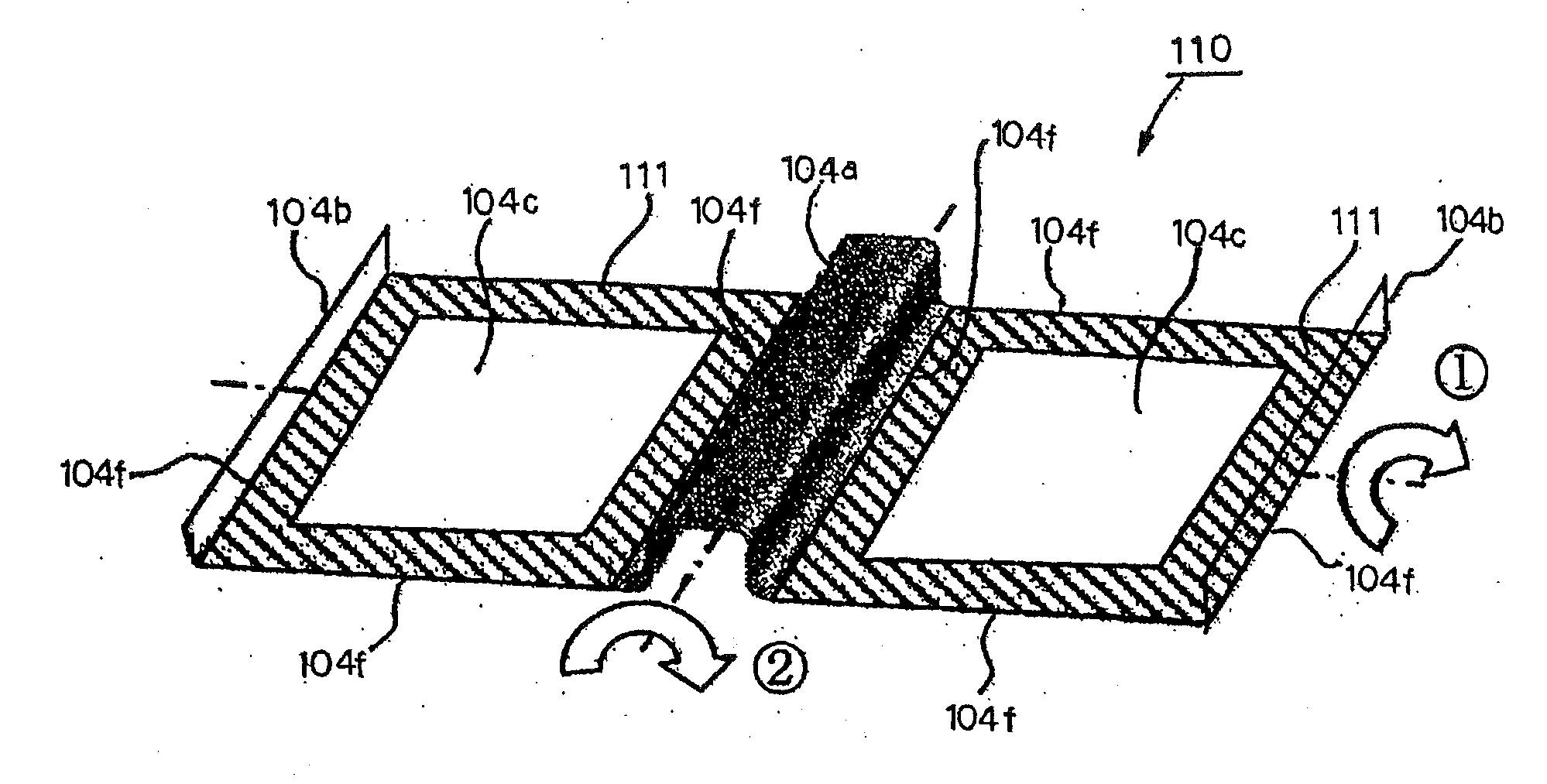
[0180]FIG. 13A is an explanatory view showing an analysis model X in which the convex-concave part 111 is formed on edges (hatching portions in FIGS. 1 and 13A) of the plane portions 104c of the front floor panel 110 shown in FIG. 1. FIG. 13B is an explanatory view showing an analysis ...

example 2

[0193]The analysis model X in which the substantially I shapes which form the convex-concave part 111 in the edges (the hatching portions in FIGS. 1 and 13A) of the plane portions 104c of the front floor panel 110 were constructed in two rows, an analysis model X-1 in which the substantially I shapes were constructed in one row, and an analysis model X-3 in which the substantially I shapes were formed in three rows were compared. The constraint conditions and the torsional directions were designated as the same as in example 1. The detailed conditions of the analysis models X, X-1 and X-3 will be shown.

[0194]The sheet thicknesses of the analysis models X, X-1 and X-3: 0.55 mm

[0195]The areas of the convex-concave parts formed in the analysis models X, X-1 and X-3: 43% of the plane portion 104c in each

[0196]The convex-concave shapes 111 of the analysis models X, X-1 and X-3: A:B:A=1:1:1

[0197]The heights of the convex-concave shapes 111 of the analysis models X and X-1: H1=H2=1.1 mm

[01...

example 3

[0203]Torsional stiffness was analyzed similarly to example 1 with respect to the front floor panel with a sheet thickness of 0.55 mm, in which the widths of the edges of the plane portion 104c were designated as 24, 36 and 48 mm, where the convex-concave part 111 was formed with A:B:A=1:1:1, θ1=θ2=30°, and the number of the substantially I shapes included in the width direction was designated as two, and the front floor panel with a sheet thickness of 0.65 mm in which the convex-concave part 111 was not formed.

[0204]FIG. 15A is a graph showing a relationship of the width of the convex-concave part, and the torsional stiffness in the direction of the circled number 1, of the front floor panel. FIG. 15B is a graph showing a relationship of the width of the convex-concave part, and the torsional stiffness in the direction of the circled number 2, of the front floor panel.

[0205]As shown in the graphs in FIG. 15A and FIG. 15B, it has been found out that the width is designated as at lea...


PUM

PropertyMeasurementUnit
inclination angle θ2aaaaaaaaaa
thicknessaaaaaaaaaa
thicknessaaaaaaaaaa

Abstract

A front floor panel for an automotive body as a lightweight sheet can be reliably press-formed without a press forming loads becoming excessively large, can have desired stiffness, and noise and vibration characteristics for all directions since there is little stiffness anisotropy. The front floor panel includes a floor tunnel formed in a center in an automotive width direction to be oriented to a longitudinal direction, upright flanges disposed left and right formed at a left and right end portions in the automotive width direction to be joined to side sills, and a left and right plane portions formed between the upright flanges disposed left and right and a left and right longitudinal wall portions of the floor tunnel. In loop-shaped areas including outer edge portions of the plane portions, convex-concave parts in specific shapes are formed, and remaining areas excluding the loop-shaped areas are formed into flat sheet shapes.

Description

TECHNICAL FIELD[0001]This invention relates to a front floor panel. Specially, the present invention relates to a front floor panel that configures a platform of an automotive body.BACKGROUND ART[0002]Most of the present automotive bodies are configured with monocoque bodies, each of which is formed by integrating a frame and a body that typically constitute a frame body, and the lower part of the body has a structure called a platform. FIG. 19 is an explanatory view schematically showing a structure of a platform 102 of an automotive body 101 in a simplified form.[0003]As shown in this drawing, the platform 102 of the automotive body 101 is disposed in a part corresponding to the conventional frame. A dash panel 103 and a front floor panel 104 of the platform 102 are joined to each other with respective edge portions overlapped on each other, and the front floor panel 104 and a rear floor panel 106 are joined to each other with respective edge portions overlapped on each other.[000...

Claims


Application Information

Patent Timeline
Patent Type & Authority Applications(United States)
IPC IPC(8): B62D25/20B21D47/00B21D53/88B21D22/02
CPCB62D25/20B21D53/88B21D47/00B21D22/02B62D25/2018
Inventor YONEBAYASHI, TORUSUZUKI, TOSHIYANAKAZAWA, YOSHIAKITAKAHASHI, MASAYA
Owner NIPPON STEEL CORP
Learn More