
Methods and systems for generating electrical property maps of biological structures

a biological structure and electrical property technology, applied in the field of combining multiple images of a biological structure, can solve the problems of putting patients at risk of unwanted and unknown side effects, reducing stimulus levels still exceeding normal physiological levels, and causing movement risk factors

Active Publication Date: 2016-04-12
AAKEN LAB
View PDF79 Cites 17 Cited by
  • Summary
  • Abstract
  • Description
  • Claims
  • Application Information

AI Technical Summary

Problems solved by technology

Unfortunately, transcranial electrical stimulation has generally required high voltages with diffuse current spread that causes the activation of large regions of the brain and puts the patient at risk of unwanted and unknown side effects.
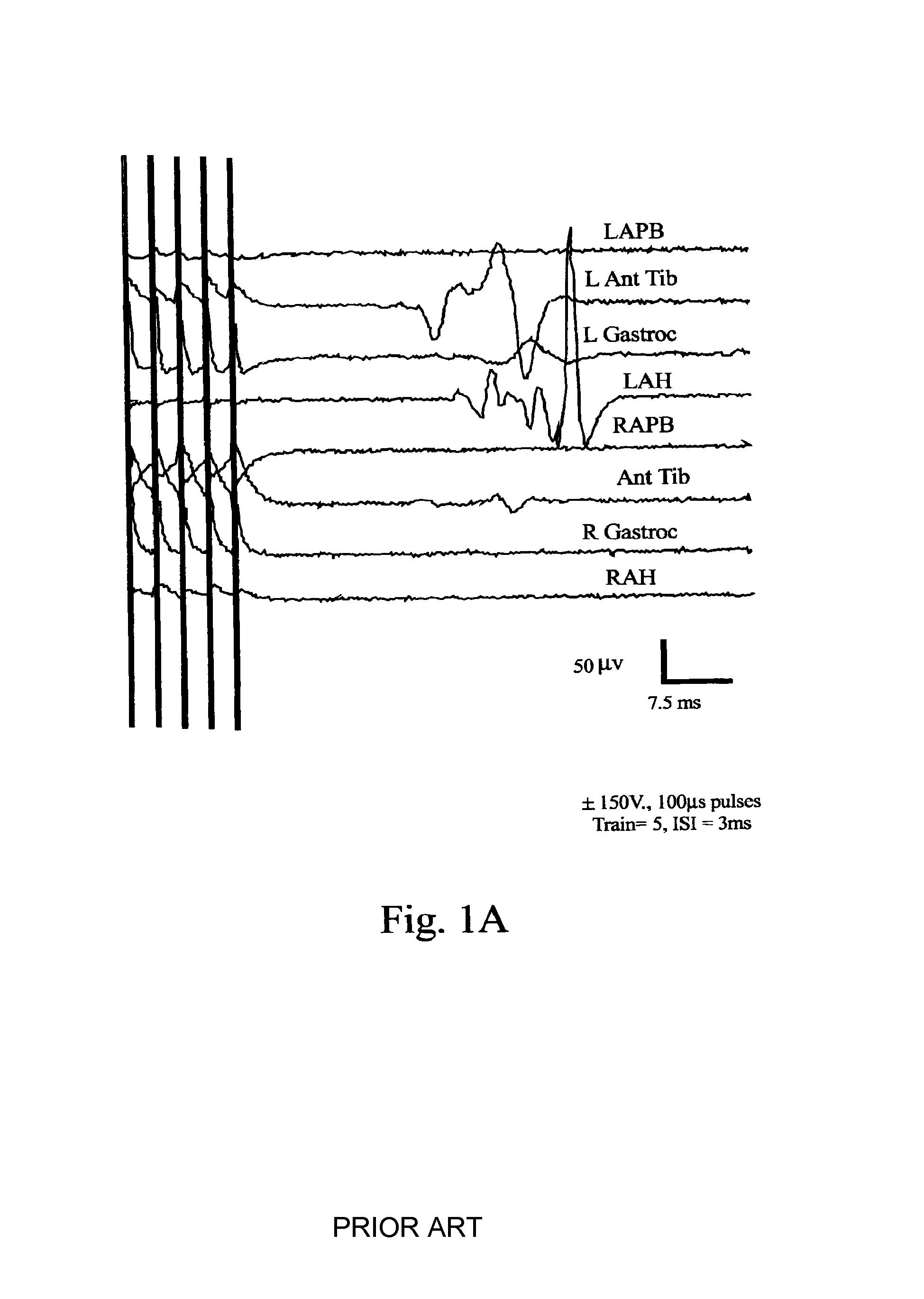
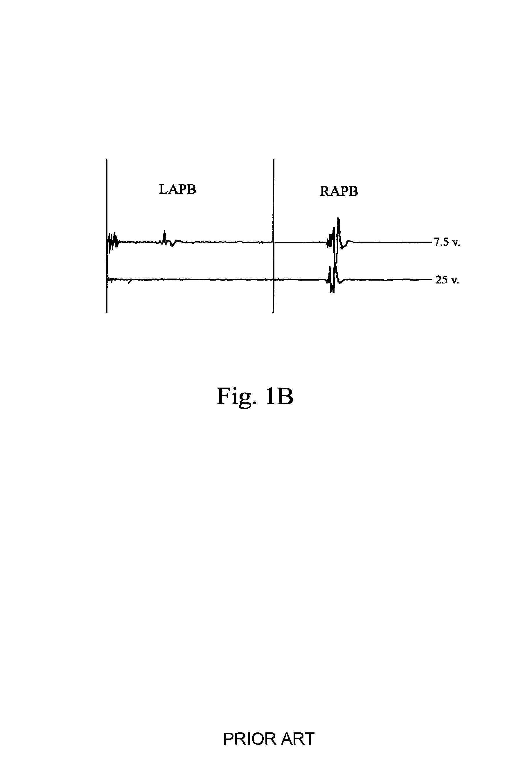
Unfortunately, the high voltages typically used to induce tcMEPs and the responses they produce can activate whole regions of the head, body, or trunk as well as the target muscles.
The movement of large muscle groups due to the uncontrolled current spread means that seizures, broken jaws and patient movement create risk factors that have been associated with tcMEP testing (see Chappa, K H, 1994, citation below).
However, these reduced stimulus levels still exceed normal physiological levels and the uncontrolled movement of large muscle groups suggests that the applied pulses continue to result in significant current spreads.
The large muscle movements that are sometimes associated with tcMEPs also limit the usefulness of the tcMEPs during periods when the surgeon is involved in delicate brain or spinal procedures.
Finding the current path through this medium has been a significant problem in neurophysiology.
They are not sufficient to represent the complexity of the problem and do not account for individuals' anatomical differences.
Although magnetic stimulators are commonly used in clinics, they have been rejected for surgical applications because of the difficulty in using them in an environment with multiple metal objects and their tendency for the stimulation parameters to be less consistent than those produced by electrical stimulation.
Small movements of the magnetic pulse generators have resulted in significant changes in the stimulus parameters and the coil cannot be used for chronic conditions wherein treatment would involve continuous stimulation.

Method used


Image

  • Methods and systems for generating electrical property maps of biological structures
  • Methods and systems for generating electrical property maps of biological structures
  • Methods and systems for generating electrical property maps of biological structures

Examples


Embodiment Construction

Abbreviations

[0059]CT=X-ray Computed Tomography[0060]GETs=Guided Electrical Transcranial stimulation[0061]EEG=Electroencephalogram[0062]MRI=Magnetic Resonance Imaging[0063]T1 MRI=T1-weighted MRI[0064]T2 MRI=T2-weighted MRI[0065]PD MRI=Proton density weighted MRI (also known as spin density weighted MRI)[0066]FE=Finite Element method[0067]SEP=Somatosensory Evoked Potentials[0068]fMRI=functional Magnetic Resonance Imaging[0069]tcMEP=transcranial Motor Evoked Potentials

Introduction

[0070]As will be described in more detail below, solutions to the forward problem are achievable with matrix algebra by constructing a model of sufficient detail representing all the heterogeneities found within an individual's head and brain. The approach described below in the Detailed Description section has bypassed the use of a physical model and uses an individual's MRI and / or CT scan as a representation of the head and brain. MRI images and CT scans are digitized images that can be manipulated through ...


PUM


Abstract

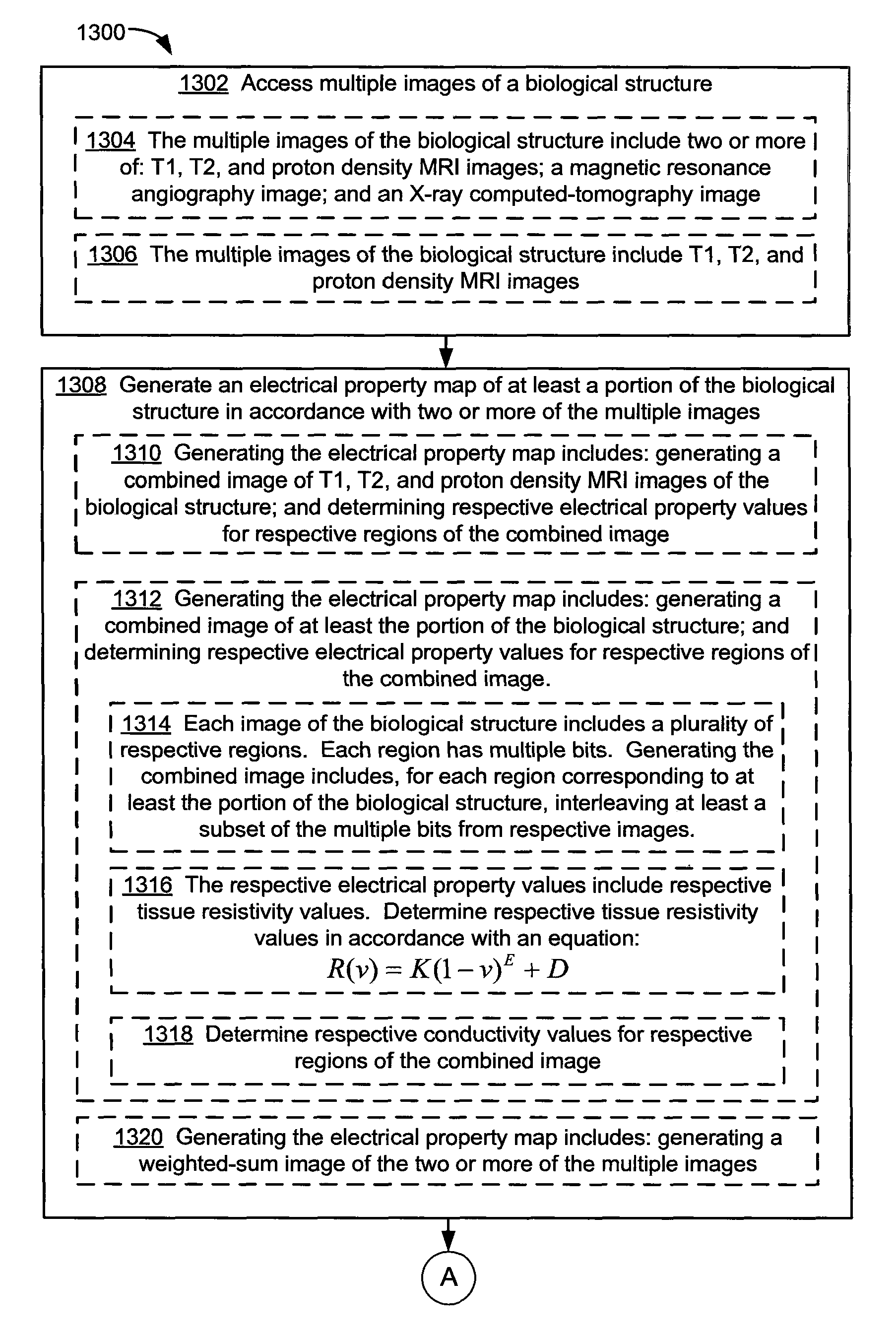
A method performed at a computer system having one or more processors and memory storing one or more programs for execution by the one or more processors is disclosed. The method includes accessing multiple images of a biological structure, generating an electrical property map of at least a portion of the biological structure in accordance with two or more of the multiple images, and providing at least a subset of the electrical property map.

Description

RELATED APPLICATIONS[0001]This application is a continuation-in-part of U.S. patent application Ser. No. 11 / 424,813, filed Jun. 16, 2006 now abandoned, which claims the benefit of priority to U.S. Provisional Patent Application Ser. No. 60 / 691,068, filed Jun. 16, 2005, both of which are incorporated by reference herein in their entirety.BACKGROUND[0002]1. Field of the Invention[0003]The invention relates to combining multiple images of a biological structure, particularly to determining electrical properties (e.g., resistivities and / or conductivities) of the biological structure from multiple images of the biological structure.[0004]2. Description of the Related Art[0005]The advent of transcranially stimulated electrical motor evoked potentials (tcMEPs) has resulted in a dramatic reduction in the rate of paralysis for high risk surgical patients (see Chappa K H, 1994, Calanchie et al 2001, Pelosi et al. 2002, Bose B, Sestokas A K, Swartz D M 2004 and MacDonald et al 2003, citations ...

Claims


Application Information

Patent Timeline
Patent Type & Authority Patents(United States)
IPC IPC(8): A61B5/055A61B5/00A61B6/00A61B6/03A61N1/36
CPCA61B5/0035A61B5/055A61B5/4064A61B6/032A61B6/5247A61N1/36017A61N1/36025A61N1/36082A61B5/004A61B5/0042A61B5/40A61B5/4058A61N1/3605A61N1/36067
Inventor RUSSELL, MICHAEL J.WILEY, DAVID F.
Owner AAKEN LAB
Learn More