Pedestrian protection device for a motor vehicle

a protection device and motor vehicle technology, applied in the direction of pedestrian/occupant safety arrangement, vehicle components, vehicular safety arrangments, etc., can solve the problem of incorrect mounting of the joint head in the joint socket, and achieve the effect of simple mounting of the joint head, improved visual recognition, and easy production

Active Publication Date: 2016-04-12
AUDI AG
View PDF21 Cites 12 Cited by
  • Summary
  • Abstract
  • Description
  • Claims
  • Application Information

AI Technical Summary

Benefits of technology

[0008]In an advantageous embodiment of the pedestrian protection device according to the invention, the joint head end region can protrude outwardly relative to the securing element with a projection. This enables a better visual recognition of the joint head end region during visual inspection and indicates the correct mounting of the joint head in the joint socket. When the joint head end region does not project outwardly relative to the securing element has with a projection the joint head is not correctly mounted in the joint socket. When mounting the actuator, the visible projection of the joint head end region can thus in a simple constructive manner immediately visually indicate the state of the mounted connection.
[0009]In a further advantageous embodiment of the pedestrian protection device according to the invention, the joint head end region of the joint head can have a round cross-section, wherein the joint head end region can for example be configured cone-shaped or cylindrical. Advantageously, the joint head with a axially symmetrical round cross-section of the joint head end region can be particularly easily produced as cold extruded part and enable a simple mounting of the joint head. The production as cold extruded part enables advantageously a sufficient strength. Thus the technically improved joint head can be produced and mounted particularly cost-effectively.
[0010]In a further advantageous embodiment of the pedestrian protection device according to the invention, the joint head and the joint socket, which receives the joint head, can be configured as plug-in connection. This advantageously enables a particularly fast and simple final mounting of the coupling joint, which in addition is configured constructively simple and as a result can be produced economically or cost-effectively. During repair work on the front flap or when exchanging the actuator, the plug-in connection enables a fast unmounting of the actuator.
[0011]In a further advantageous embodiment of the pedestrian protection device according to the invention, the plug-in connection can be configured form fittingly and / or force fittingly. This has the advantage that the joint head can be optimally supported in the joint socket and that when the activation the actuator is activated in the event of a crash, great forces can be reliably and securely transmitted via the form fitting and / or force fitting plug-in connection of the actuator.
[0012]In a further advantageous embodiment of the pedestrian protection device according to the invention, the joint head end region can at least partially form a form fitting latching connection with the recess of the joint socket and with the recess of the securing element. Advantageously, in addition to enabling the visual checking, the joint head end region have a function as fastening element of the joint head in the joint socket and a further function as a stop element to stabilize the position of the securing element in axial direction of the actuator. As a result a particularly space-saving and especially load bearing multi-connection of the coupling joint can be realized, which due to its compact construction can also be mounted in vehicles with small space conditions without having to change the dimensions of the vehicle body.
[0013]In a further advantageous embodiment of the pedestrian protection device according to the invention, the joint socket can have two slots on its outer conference which are arranged so as to oppose each other and extend in the direction of a center longitudinal axis, and into which bent ends of the securing element latchingly engage. Advantageously the joint head end region of the joint head can have at least one radially circumferential indentation on its outer circumference into which a locking ring latchingly engages, which locking ring extends radially circumferentially on the inner circumference of the securing element. This enables mounting and supporting the securing element on the joint socket in the right position relative to the joint head without great resistance in a constructively simple and a construction space saving manner. The joint socket which has the slot as well as the securing element which has the indentation can be manufactured cost-effectively as mass parts, wherein the joint socket due to the axially arranged slots can be manufactured in a simple injection molding tool and the securing element which has the indentation can be produced in a material removing process as turned part or as cold extruded part.

Problems solved by technology

When the joint head end region does not project outwardly relative to the securing element has with a projection the joint head is not correctly mounted in the joint socket.

Method used


Image

  • Pedestrian protection device for a motor vehicle
  • Pedestrian protection device for a motor vehicle
  • Pedestrian protection device for a motor vehicle

Examples


Embodiment Construction

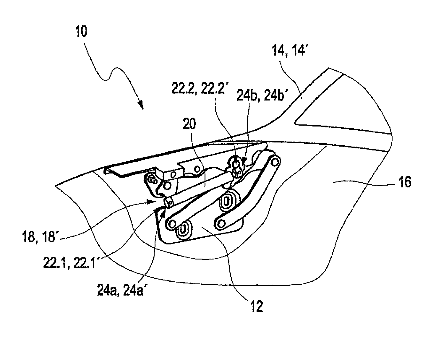
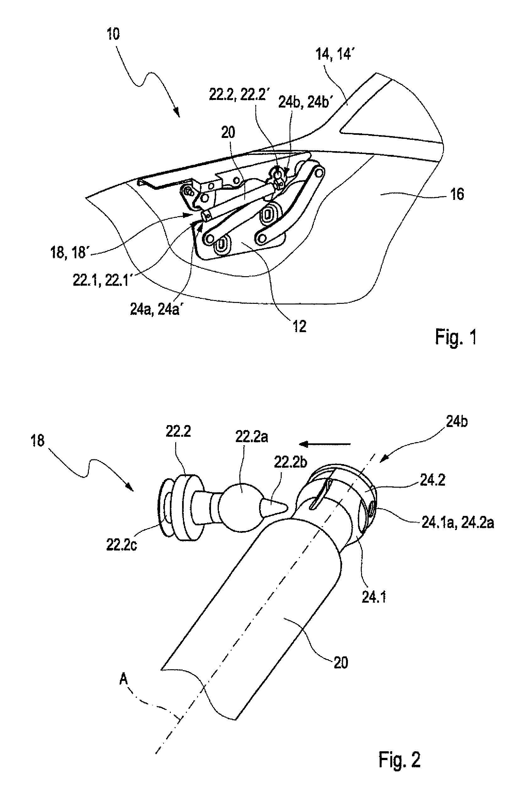
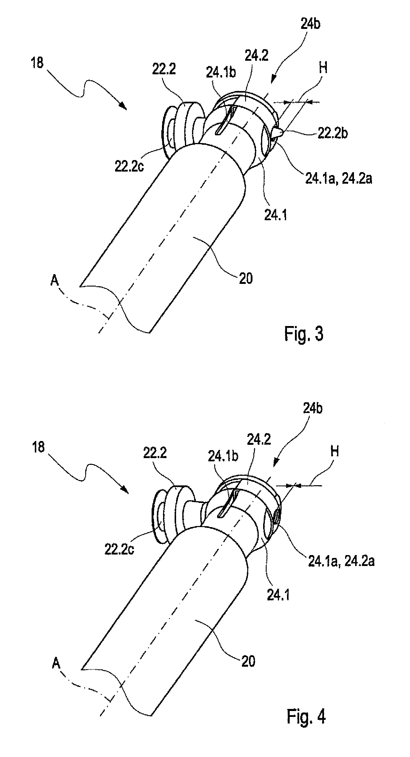
[0027]FIGS. 1 to 9 show relevant parts of the pedestrian protection device 10 for a motor vehicle with a front flap 16, which is connected with the vehicle body 14, 14′ via a coupling device 12 and an actuating device 18, 18′. Usually such a coupling device 12 and an associated actuating device 18, 18′ are arranged on both longitudinal sides of the front flap 16 in order to movably couple the front flap 16 with the motor vehicle body 14, 14′. In the shown exemplary embodiment the actuating device 18, 18′ moves the front flap 16 via an actuator 20 into a protective position, which is raised relative to the vehicle body 14, 14′ of the motor vehicle, and fixes the front flap 16 in the protective position. The actuator 20 can be connected with the coupling device 12 and the front flap 16 on both ends respectively via a coupling joint 22.1, 22.1′, 22.2, 22.2′, wherein the coupling joint 22.1, 22.1′22.2, 22.2′ includes a joint head 22.2a, 22.2a′ and a joint socket unit 24, 24a′, 24b, 24b′...


PUM


Abstract

A pedestrian protection device for a motor vehicle, includes a front flap that is connected to a body of the motor vehicle by means of at least one coupling device and at least one adjusting device, by means of which adjusting device the front flap, by way of at least one actuator, can be moved into a protective position that is raised relative to the body of the motor vehicle and can be fixed in the protective position, wherein the at least one actuator is connected to the corresponding coupling device and to the front flap by means of a coupling joint, the coupling joint including a joint head and a joint socket unit that receives the joint head, the joint socket unit having a joint socket and a retaining element that at least partially surrounds the joint socket. The joint head has a joint head end region that visibly interacts with a recess in the joint socket unit.

Description

CROSS-REFERENCES TO RELATED APPLICATIONS[0001]This application is the U.S. National Stage of International Application No. PCT / EP2013 / 000858, filed Mar. 21, 2013, which designated the United States and has been published as International Publication No. WO 2013 / 143669 A1 and which claims the priority of German Patent Application, Serial No. 10 2012 006 496.9, filed Mar. 29, 2012, pursuant to 35 U.S.C. 119(a)-(d).BACKGROUND OF THE INVENTION[0002]The invention relates to a pedestrian protection device for a motor vehicle.[0003]An adjustable pedestrian protection device, which is in particular arranged in the front region of a passenger car, is generally known. When a collision with a pedestrian or bicyclers is detected, the pedestrian protection device has the purpose to quickly raise a crash-active front flap in the region of the windshield via one or multiple pyrotechnically controlled actuators so as to assume a protective position which is raised relative to a body of the motor ve...

Claims


Application Information

Patent Timeline
Patent Type & Authority Patents(United States)
IPC IPC(8): B60R21/38
CPCB60R21/38
Inventor SCHABENBERGERS, RICHARDMAYRHOFER, GUNTHER
Owner AUDI AG
Why Eureka
Try Eureka