Process for producing 2, 3, 3, 3-tetrafluoropropene and 1, 1-difluoroethylene

a technology of tetrafluoropropene and ethylene, which is applied in the field of process for producing 2, 3, 3, and tetrafluoropropene, can solve the problems of high installation cost, difficult distillation/purification of intermediate product and final product, and insufficiently high yield of hfo-1234yf, so as to reduce the cost of raw materials and production facilities, the effect of high yield and substantial economic benefits

Active Publication Date: 2016-04-19
ASAHI GLASS CO LTD
View PDF6 Cites 0 Cited by
  • Summary
  • Abstract
  • Description
  • Claims
  • Application Information

AI Technical Summary

Benefits of technology

[0017]According to the process of the present invention, it is possible to produce HFO-1234yf useful as a new refrigerant in sufficiently high yield by using readily available R22, R40 and TFE as raw material and reacting them as they are without taking out an intermediate product from the reaction system. Accordingly, as compared with conventional methods for producing HFO-1234yf, it is possible to substantially reduce costs required for the raw material and production facilities.
[0018]Further, it is possible to prevent formation of a byproduct such as CTFE which is difficult to separate by distillation from HFO-1234yf, whereby it is possible to obtain highly pure HFO-1234yf. Further, it is possible to produce, together with HFO-1234yf, 1,1-difluoroethylene (VdF) which is useful as raw material for polyvinylidene fluoride to be used as material for water-treatment filters, various production machine components, etc., whereby economical merits are substantial. Furthermore, recycling of byproduct TFE is possible, whereby economical effects are substantial.

Problems solved by technology

However, this process has problems such that it requires multistage reactions whereby installation costs tend to be high, and distillation / purification of the intermediate product and the final product is difficult.
However, in each of the methods disclosed in Patent Documents 1 and 2, although HFO-1234yf was formed by one reaction, it was not possible to obtain highly pure HFO-1234yf in sufficiently high yield, since the amount of a byproduct formed such as chlorotrifluoroethylene (CTFE) which is difficult to separate by distillation from HFO-1234yf, tended to be large.
Further, in the method disclosed in Patent Document 2, as the retention time increased, formation of high boiling products as by-products and carbonization of raw material were likely to occur whereby the reactor was likely to get blocked.
Further, by the influence of an acid component formed as a byproduct, a special corrosion resistant apparatus (such as a reaction tube lined with platinum) was required, and thus, in consideration of the industrial production, such a method was totally unrealistic.

Method used


Image

  • Process for producing 2, 3, 3, 3-tetrafluoropropene and 1, 1-difluoroethylene
  • Process for producing 2, 3, 3, 3-tetrafluoropropene and 1, 1-difluoroethylene
  • Process for producing 2, 3, 3, 3-tetrafluoropropene and 1, 1-difluoroethylene

Examples


example 1

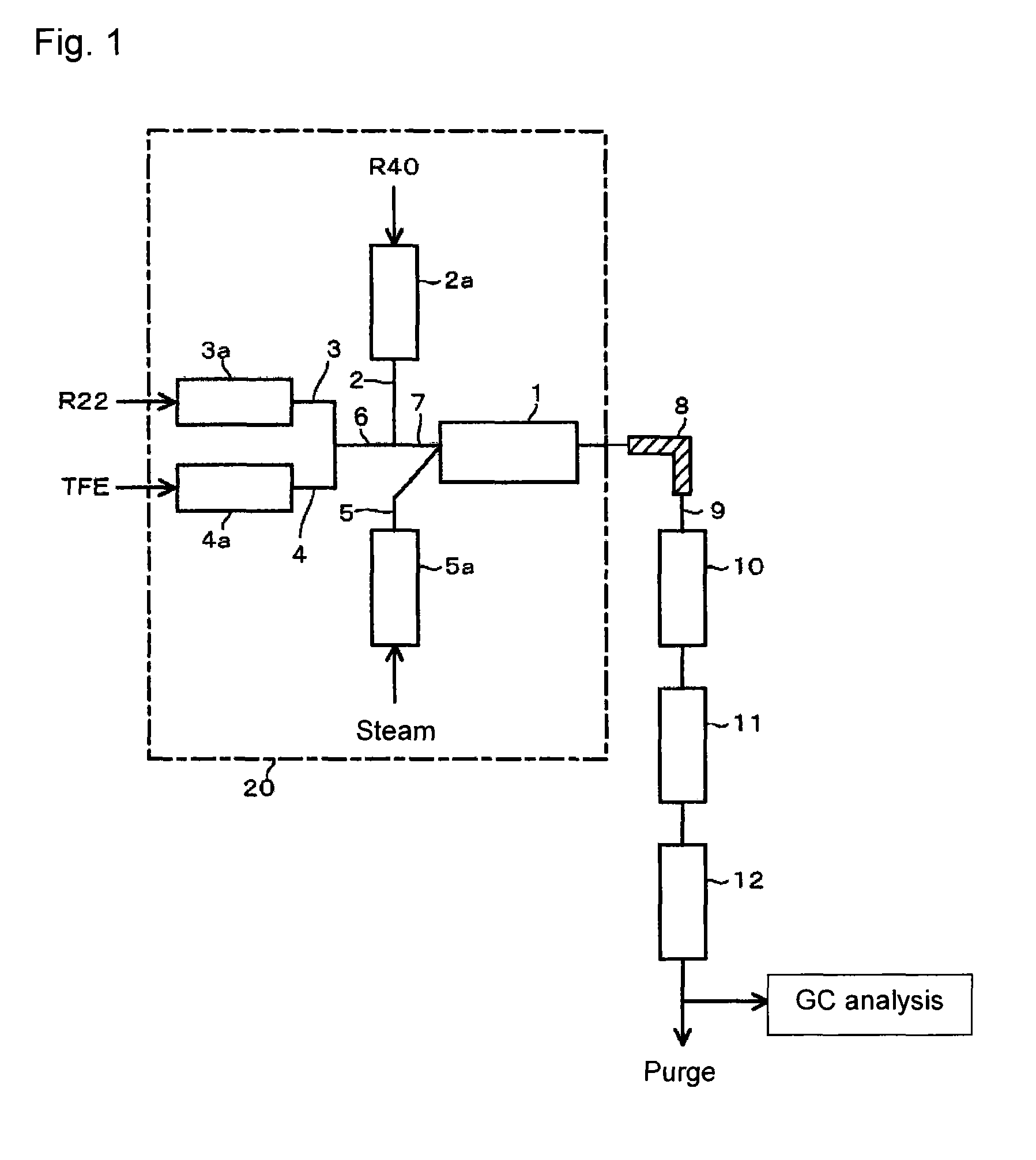
[0066]Using the reaction apparatus as shown in FIG. 1, from a raw material gas comprising R22, R40 and TFE, crude HFO-1234yf and crude VdF were obtained as follows.

[0067]Into a stainless steel tube in an electric furnace set at an internal temperature of 300° C., R40 was continuously introduced, and R40 was heated (preheated) to 300° C. Further, into a stainless steel tube in an electric furnace set at an internal temperature of 300° C., R22 was continuously introduced, and R22 was preheated to 300° C. Furthermore, into a stainless steel tube in an electric furnace set at an internal temperature of 300° C., TFE was continuously introduced, and TFE was preheated to 300° C.

[0068]These preheated raw material gas components (R40, R22 and TFE) and steam (water vapor) heated by an electric furnace set at an internal temperature of 750° C. were supplied to a reactor controlled to have an internal pressure (gauge pressure) of 0.04 MPa and an internal temperature of 800° C., so that the mola...

examples 2 to 4

[0081]The molar ratio (TFE / (TFE+R22)) of the supply amount of TFE to the total supply amount of TFE and R22 was made to be 0.1 (10%) in Example 2, 3 (30%) in Example 3 and 0.7 (70%) in Example 4. Further, so that the equivalent ratio of R40 / (TFE+R22) would be 0.5, the molar ratio of R40 / (TFE+R22) was made to be 0.55 in Example 2, 0.65 in Example 3 and 0.85 in Example 4. Otherwise, the reaction was conducted under the same conditions as in Example 1.

[0082]Then, the gas of the reaction mixture withdrawn from the outlet of the reactor was cooled to at most 100° C. and subjected to recovery of steam and the acidic liquid and alkaline cleaning sequentially and then to dehydration treatment, whereupon the obtained outlet gas was analyzed by gas chromatography, and the molar composition of the gas components contained in the outlet gas was calculated. Further, based on the obtained molar composition of the outlet gas, the conversion (reaction rate) of R40, the selectivity of each component...

example 5

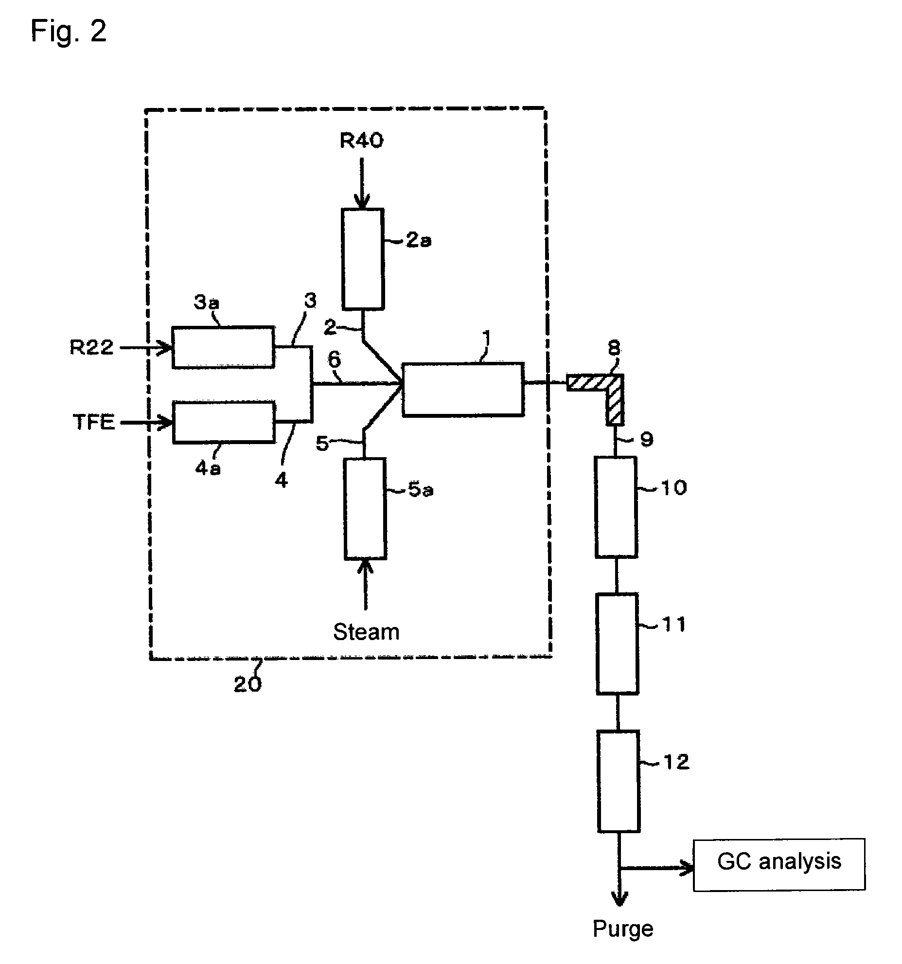
[0087]Without conducting preheating of R40, R22 and TFE, the respective raw material components at room temperature (10° C.) were supplied as they were, to the reactor. Otherwise, the reaction was conducted under the same conditions as in Example 1.

[0088]Then, the gas of the reaction mixture withdrawn from the outlet of the reactor was cooled to at most 100° C. and subjected to recovery of steam and the acidic liquid and alkaline cleaning sequentially and then to dehydration treatment, whereupon the obtained outlet gas was analyzed by gas chromatography, and the molar composition of the gas components contained in the outlet gas was calculated. Based on the obtained molar composition of the outlet gas, the conversion (reaction rate) of R40, the selectivity of each component derived from R40, the conversion (reaction rate) of R22 and / or TFE, the selectivity of each component derived from R22 and / or TFE, and the ratio of HFO-1234yf to CTFE (HFO-1234yf / CTFE) were, respectively, obtaine...


PUM

PropertyMeasurementUnit
temperatureaaaaaaaaaa

Abstract

To provide an economically advantageous process for producing HFO-1234yf useful as a new refrigerant in sufficiently high yield by one reaction involving thermal decomposition. A process for producing HFO-1234yf and VdF from raw material containing R22, R40 and TFE, by a synthetic reaction involving thermal decomposition, which comprises (a) a step of supplying the R22, the R40 and the TFE to a reactor, as preliminarily mixed or separately, (b) a step of supplying a heat medium to the reactor, and (c) a step of bringing the heat medium in contact with the R22, the R40 and the TFE in the reactor to form the HFO-1234yf and the VdF.

Description

[0001]This application is a CON of PCT / JP2013 / 057258, filed Mar. 14, 2013.TECHNICAL FIELD[0002]The present invention relates to a process for producing 2,3,3,3-tetrafluoropropene and 1,1-difluoroethylene, particularly to a process for producing 2,3,3,3-tetrafluoropropene and 1,1-difluoroethylene by one reaction from raw material comprising chlorodifluoromethane, chloromethane and tetrafluoroethylene.BACKGROUND ART[0003]In recent years, 2,3,3,3-tetrafluoropropene (HFO-1234yf) has attracted attention as a new refrigerant to replace 1,1,1,2-tetrafluoroethane (HFC-134a) which is a greenhouse gas. In this specification, with respect to a halogenated hydrocarbon, after its chemical name, an abbreviated name of the compound is shown in brackets, and in this specification, as the case requires, instead of the chemical name, its abbreviated name is used.[0004]As a process for producing HFO-1234yf, for example, a process is known wherein 1,1-dichloro-2,2,3,3,3-pentafluoropropane (HCFC-225ca) ...

Claims


Application Information

Patent Timeline
Patent Type & Authority Patents(United States)
IPC IPC(8): C07C17/269C07C17/25
CPCC07C17/25C07C17/269C07C21/18
Inventor FURUTA, SHOJITAKEUCHI, YU
Owner ASAHI GLASS CO LTD
Why Eureka
Try Eureka