Networking systems with dynamically changing topologies

a network system and dynamic topology technology, applied in the field of changing the topology of the computer network, can solve problems such as negate the benefi

Active Publication Date: 2016-04-19
GOOGLE LLC
View PDF15 Cites 19 Cited by
  • Summary
  • Abstract
  • Description
  • Claims
  • Application Information

AI Technical Summary

Benefits of technology

[0016]According to another aspect, the system described herein relates to carrying out at least the method described above. In certain embodiments, the system comprises a patch panel manager, a network element manager, a wiring verification component, a solver, and a sequencer. The patch panel manager programs the smart patch panel, which in certain embodiments may be an optical circuit switch, to implement a logical topology for the computer network. The network element manager monitors a status of and programs a traffic routing plan into the software-configured packet switch, and in certain embodiments may be an OpenFlow controller. The wiring verification component determines the connectivity of the smart patch panel to other elements in the computer network, in certain embodiments by coordinating actions of the patch panel manager and the network element manager. The solver responds to a network event by identifying an alternative logical topology based on the determined connectivity of the smart patch panel, the status of the software-configured packet switch, and a network performance target. The network event may include a network administrator request, a failure to meet a network performance target, a change in network traffic, a change in a connection status of a network element, a change in a connection status of the smart patch panel, or some other predetermined network event. The solver generates one or more alterations to the logical topology and the traffic routing plan for implementing the alternative logical topology. The alterations to the traffic routing plan may include routing traffic among the network elements to preempt disruption by a logical topology alteration, instructing the smart patch panel to implement the logical topology alteration, and rerouting network traffic to take advantage of the newly adopted logical topology. The sequencer coordinates the network element manager and the patch panel manager to implement the alternative logical topology by coordinating the alterations generated by the solver.

Problems solved by technology

The period of delayed or lost network traffic following a network link change generally negates the benefit of changing a network to a more efficient topology.

Method used


Image

  • Networking systems with dynamically changing topologies
  • Networking systems with dynamically changing topologies
  • Networking systems with dynamically changing topologies

Examples


Embodiment Construction

[0027]In the following description, numerous details are set forth for the purpose of explanation. However, one of ordinary skill in the art will realize that the embodiments described herein may be practiced without the use of these specific details and that the embodiments described herein may be modified, supplemented, or otherwise altered without departing from the scope of the invention.

[0028]The systems and methods described herein improve network performance by using centralized control to respond to a network event by altering both the logical topology and traffic routing plan of the network while avoiding network disruptions. By routing network traffic away from links that will be broken by a logical topology adjustment and updating the traffic routing plan upon the completion of a logical topology change, a network may adopt a more efficient logical topology without misdirecting network traffic.

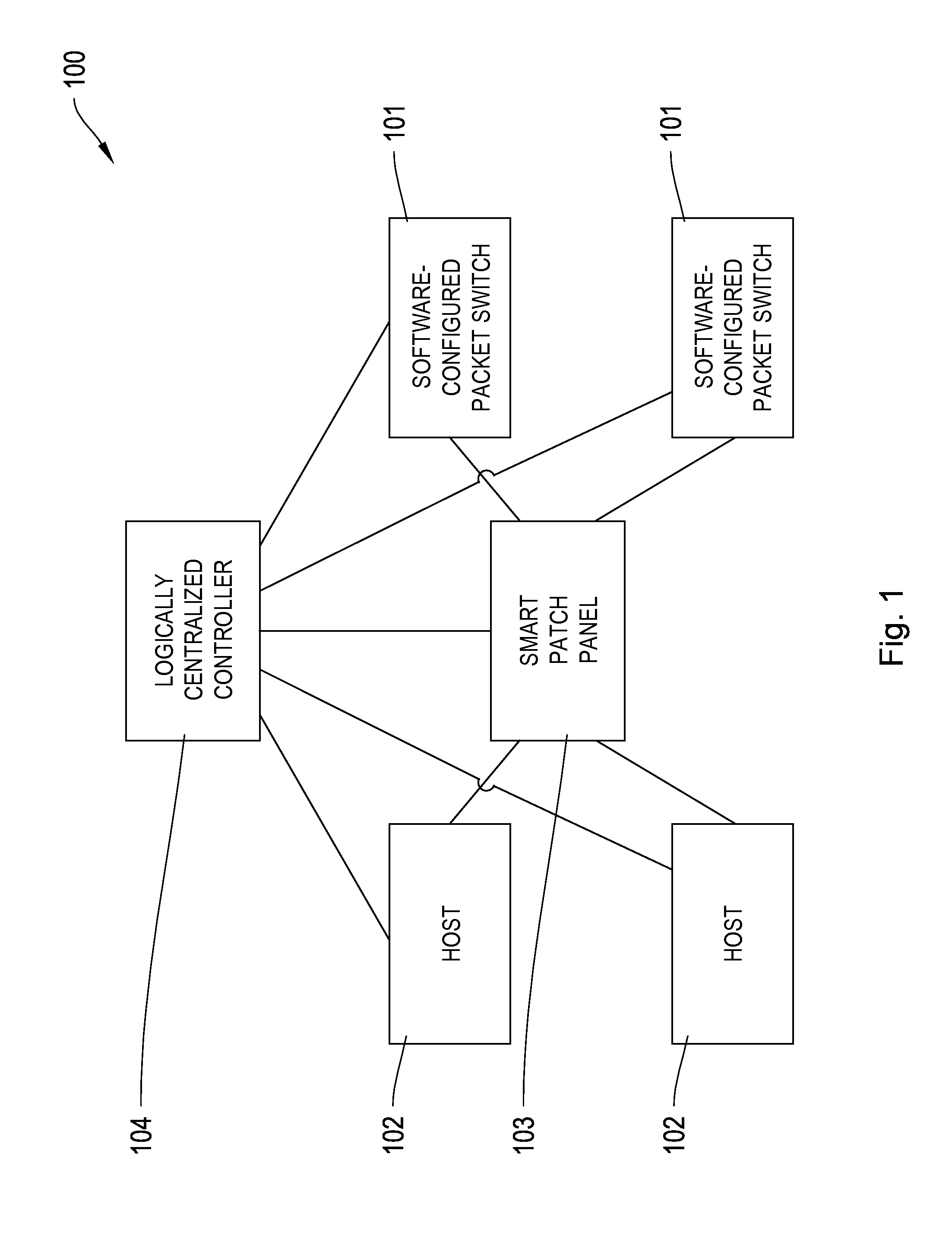
[0029]FIG. 1 is an illustrative diagram of a network 100 with a flexible topolo...


PUM


Abstract

Network performance may be improved by adjusting a logical network topology while avoiding attendant disruptions. By identifying an alternative logical topology, routing network traffic away from links that will be eliminated from the alternative logical topology, and updating a traffic routing plan upon the adoption of the alternative logical topology, a network may adopt a more efficient topology without misdirecting network traffic.

Description

FIELD OF THE INVENTION[0001]The systems and methods described herein relate to changing topology of a computer network, and particularly, to changing a data-center network topology to improve network performance.BACKGROUND[0002]Many modern communications require computer networks. It is infeasible to directly connect every computer to every other computer with which it might exchange emails, videos, financial transactions, or other information. Computers are instead connected to each other via switches, devices which receive data from a computer, determine an intended destination of the received data, and transmit the received data towards the destination. Computers and switches are collectively referred to as network elements, and are connected by links, and the pattern of the links between the network elements is called the network topology.[0003]Switches are generally programmed to route a packet through the fastest available path through the network topology and to a network des...

Claims


Application Information

Patent Timeline
Patent Type & Authority Patents(United States)
IPC IPC(8): H04L12/28H04L29/08H04L12/24
CPCH04L29/08315H04L41/082H04L45/64H04L45/02H04L41/122H04L41/12H04L67/1042
Inventor POUTIEVSKI, LEONVAHDAT, AMINNAIK, ASHISH
Owner GOOGLE LLC
Why Eureka
Try Eureka