Modular lag screw

a technology of lag screw and module, applied in the field of implants, can solve the problems of pain, irritation and/or injury of surrounding soft tissue, and achieve the effect of reducing the irritation of surrounding tissu

Active Publication Date: 2016-04-26
STRYKER EURO OPERATIONS HLDG LLC
View PDF23 Cites 3 Cited by
  • Summary
  • Abstract
  • Description
  • Claims
  • Application Information

AI Technical Summary

Benefits of technology

[0006]One aspect of the invention may be defined as providing an implant causing less irritation of surrounding tissue when being implanted.
[0010]Such a combination of parts as an implant allows the surgeon to shorten the implant once protrusion of the implant out of for example a bone has occurred due to bone fragment compression. Such a shortening may be accomplished in a short procedure leaving at least the distal part of the implant in place which may be crucial as the probability of removal, patient outcome and stability are influenced by the implant. Accordingly, an implant is provided which can be assembled pre-operatively with a distal part and a proximal part, either at the time of manufacture or in the operating room, and can be disassembled by a smaller surgery merely removing the proximal part.
[0013]According to one embodiment, the distal part engagement portion of the proximal part is formed so as to provide a form-fit with the tool engagement portion of the distal part. It can be seen as an advantage of a form-fit connection that no gaps or free edges may exist between the distal and proximal parts.

Problems solved by technology

However, due to the anatomical variation of bones it may happen that the trailing end of a bone implant extends out of a bone after implant placement.
It may occur that patients complain about pain after surgery in this area, especially when the implant is extending out of the bone.
This pain may be caused by sharp edges at the trailing end of the implant.
Such edges may cause irritation and / or injury to the surrounding soft tissue.

Method used


Image

  • Modular lag screw
  • Modular lag screw
  • Modular lag screw

Examples


Embodiment Construction

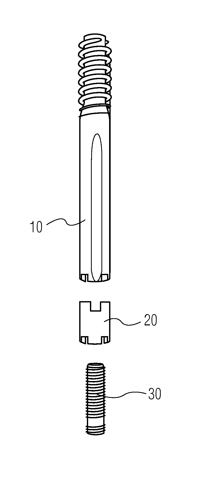
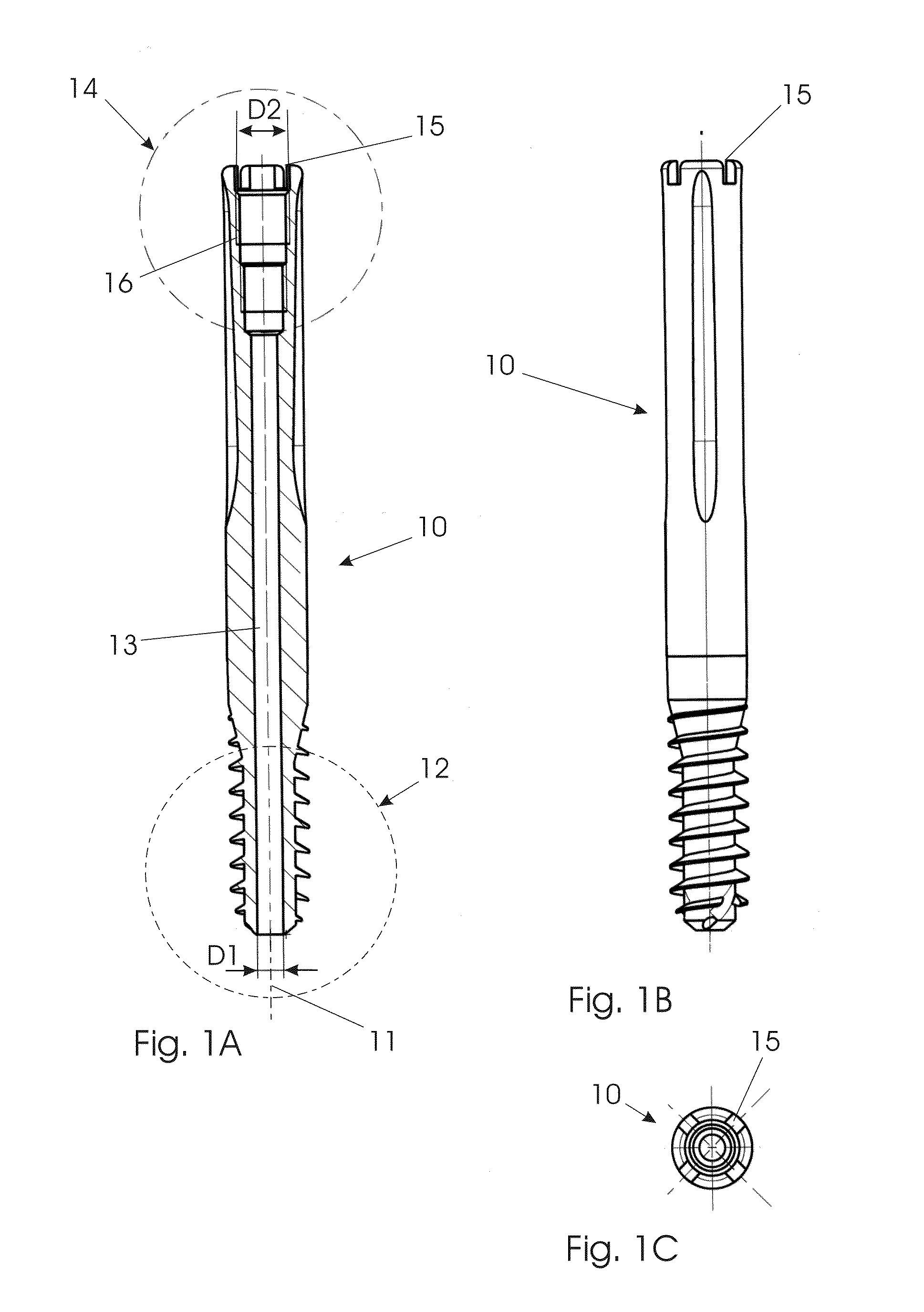
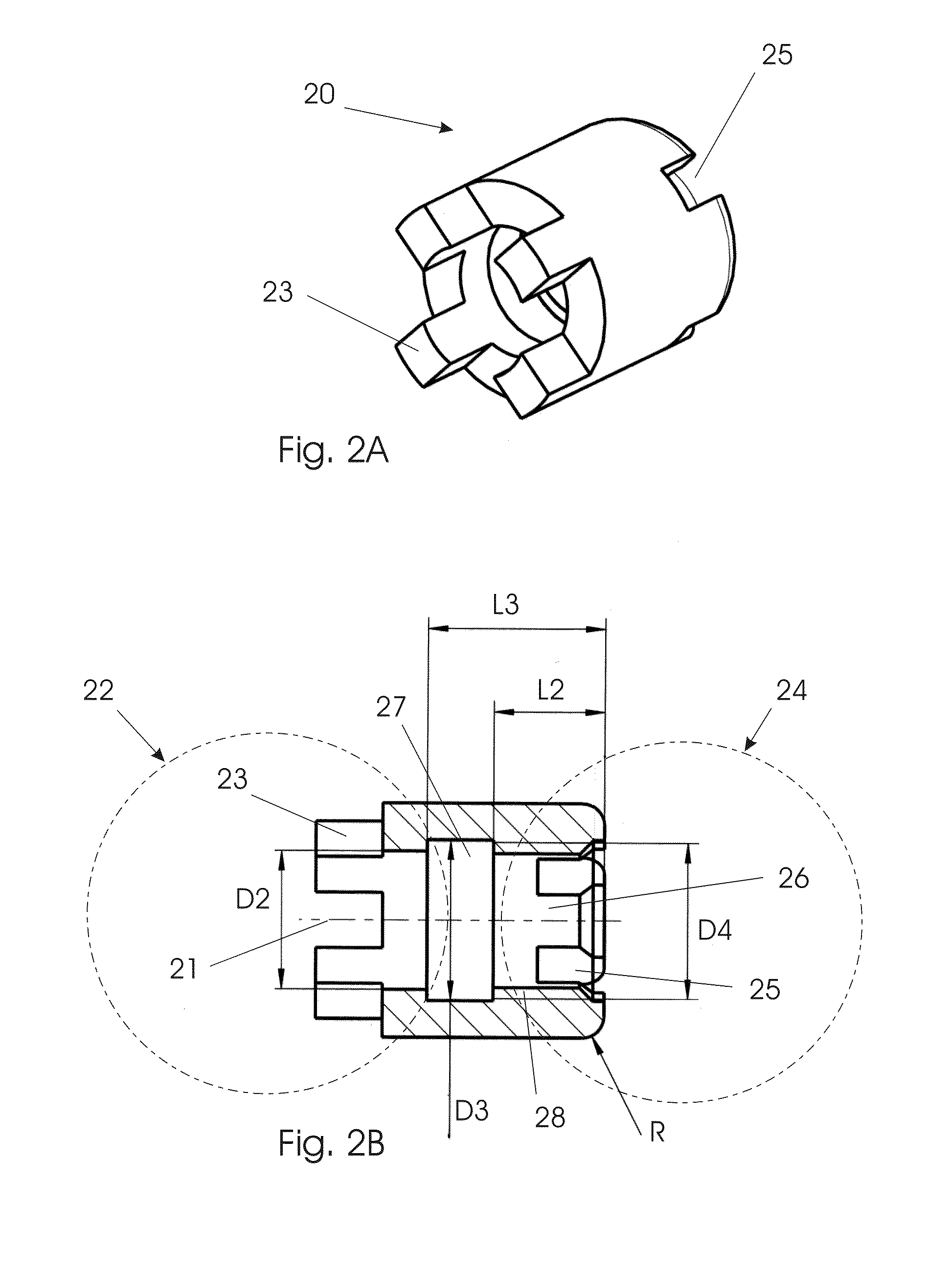
[0033]Embodiments of an implant are shown in the FIGS. and described below, comprising a bone screw as a distal part, two different proximal parts as bone screw extensions as well as two different assembly screws for coupling at least one of the proximal parts with the distal part.

[0034]In general, the distal part 10 as well as the assembly element 30 comprises an axial through bore 13 having a diameter D1, for accommodating a guide wire. At the trailing section of the distal part 10, a threaded bore 16 with an outer diameter D2 is provided, for receiving outer threads of an assembly element 30 having a corresponding diameter D2′ (FIG. 4B). The proximal part 20 also includes a bore section with a diameter D2 allowing an assembly element 30 to extend through that bore section of the proximal part 20. Furthermore, the proximal part 20 includes an enlarged bore section having a diameter D3 for accommodating a head 31 of the assembly element 30 having an outer diameter D3′ which is slig...


PUM


Abstract

An elongated modular implant is provided which has a distal part and a proximal part both having a leading end and a trailing end, respectively. The trailing end of the distal part includes a tool engagement portion and the leading end of the proximal part includes a distal part engagement portion for an engagement with the tool engagement portion of the distal part. The implant further includes an assembly element for firmly coupling the distal part and the proximal part when the first tool engagement portion of the distal part engages the distal part engagement portion of the proximal part. The proximal part trailing end may also have a tool engagement portion identical to the trailing end of the distal part.

Description

BACKGROUND OF THE INVENTION[0001]The invention relates to an implant. In particular, the invention relates to a bone screw like a lag screw to be received in a transverse through bore in a bone nail or hip plate.[0002]An implant and particularly a bone implant include a portion or section or end which is adapted to be firstly introduced into a body during an implantation. In the description below, such a portion or section or end is referred to as leading portion or leading section or leading end. Consequently, an opposite portion or section or end of the implant is adapted to be introduced last, wherein this portion or section or end may additionally be configured for an engagement of a tool for inserting the implant into the body. Below, such a portion or section or end is referred to as trailing portion or trailing section or trailing end.[0003]A bone implant may be a pin or a nail or screw or plate. A bone nail may be an intramedullary nail, for example a femur nail, a humerus n...

Claims


Application Information

Patent Timeline
Patent Type & Authority Patents(United States)
IPC IPC(8): A61B17/04A61F2/08A61B17/86A61B17/74
CPCA61B17/744A61B17/8685A61B17/8605
Inventor PROBE, ROBERTPAULSEN, MARTJESIMON, BERND
Owner STRYKER EURO OPERATIONS HLDG LLC
Why Eureka
Try Eureka