System and method for inexsufflating a subject

a subject and system technology, applied in the field of inexsufflation of subjects, can solve the problems of difficulty to achieve effective coughing on their own, inability to provide confirmation of acceptable settings, and inability to determine initial (optimal) settings for a particular patient, etc., to achieve the effect of reducing the pressure of the pressurized flow

Active Publication Date: 2016-04-26
KONINK PHILIPS ELECTRONICS NV
View PDF14 Cites 4 Cited by
  • Summary
  • Abstract
  • Description
  • Claims
  • Application Information

AI Technical Summary

Benefits of technology

[0012]These and other objects, features, and characteristics of the present disclosure, as well as the methods of operation and functions of the related elements of structure and the combination of parts and economies of manufacture, will become more apparent upon consideration of the following description and the appended claims with reference to the accompanying drawings, all of which form a part of this specification, wherein like reference numerals designate corresponding parts in the various figures. In one embodiment, the structural components illustrated herein are drawn to scale. It is to be expressly understood, however, that the drawings are for the purpose of illustration and description only and are not a limitation. In addition, it should be appreciated that structural features shown or described in any one embodiment herein can be used in other embodiments as well. It is to be expressly understood, however, that the drawings are for the purpose of illustration and description only and are not intended as a definition of limits.

Problems solved by technology

Some people, due to injury, disease, or even thoracic surgery, find it difficult to impossible to cough effectively on their own.
In conventional systems, determining the initial (optimal) settings for a particular patient can be imprecise and / or inaccurate.
Conventional systems may not provide confirmation that acceptable settings have been reached.

Method used


Image

  • System and method for inexsufflating a subject
  • System and method for inexsufflating a subject
  • System and method for inexsufflating a subject

Examples


Embodiment Construction

[0018]As used herein, the singular form of “a”, “an”, and “the” include plural references unless the context clearly dictates otherwise. As used herein, the statement that two or more parts or components are “coupled” shall mean that the parts are joined or operate together either directly or indirectly, i.e., through one or more intermediate parts or components, so long as a link occurs. As used herein, “directly coupled” means that two elements are directly in contact with each other. As used herein, “fixedly coupled” or “fixed” means that two components are coupled so as to move as one while maintaining a constant orientation relative to each other.

[0019]As used herein, the word “unitary” means a component is created as a single piece or unit. That is, a component that includes pieces that are created separately and then coupled together as a unit is not a “unitary” component or body. As employed herein, the statement that two or more parts or components “engage” one another shal...


PUM


Abstract

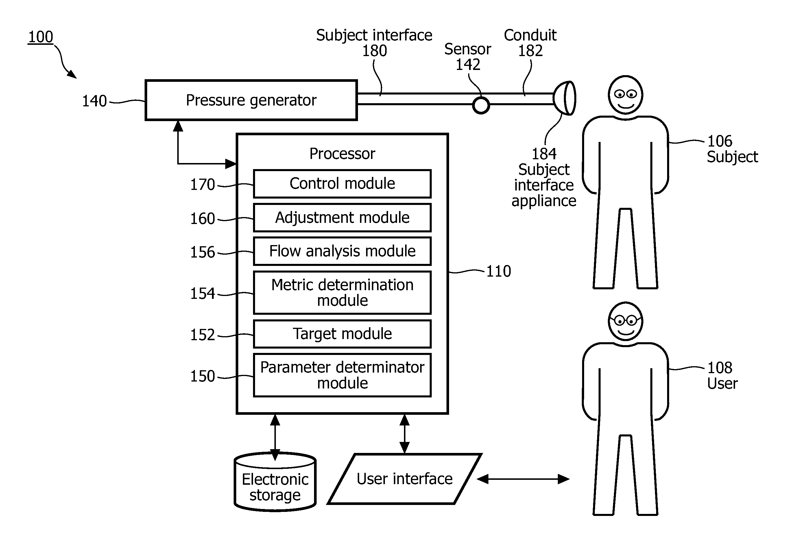
A system for controlling machine-induced expiratory airflow of a subject, the subject having an airway, the system comprising: a pressure generator (140) configured to generate a pressurized flow of breathable gas for delivery to the airway of the subject; and one or more processors (110) configured to execute computer program modules, the computer program modules comprising: a control module (170) configured to control the pressure generator a metric determination module (154) configured to determine a value of a flow metric during expiration by the subject, a flow analysis module (156) configured to compare the determined value of the flow metric with a target level of the flow metric; and an adjustment module (160) configured to adjust one or more of exsufflation pressure.

Description

CROSS-REFERENCE TO RELATED APPLICATIONS[0001]This patent application claims the priority benefit under 35 U.S.C. §371 of international patent application no. PCT / IB2011 / 055726, filed Dec. 16, 2011, which claims the priority benefit under 35 U.S.C. §119(e) of U.S. Provisional Application No. 61 / 425,392 filed on Dec. 21, 2010, the contents of which are herein incorporated by reference.BACKGROUND OF THE INVENTION[0002]1. Field of the Disclosure[0003]The invention relates to inexsufflation of a subject during which peak expiratory flow rate is controlled.[0004]2. Description of the Related Art[0005]Coughing, also known as “airway clearance”, is a normal function of everyday life for most people. Inhaled air is drawn in slowly (<1 LPS). Then, the glottis closes and the expiratory muscles contract, increasing the subglottic pressure. To begin the cough, the glottis opens and the initial flow is the decompression of the air in the trachea. The lungs continue to empty at a rate of roughl...

Claims


Application Information

Patent Timeline
Patent Type & Authority Patents(United States)
IPC IPC(8): A61M11/00A61M16/06A61M16/08A61M16/04A61M16/00
CPCA61M16/0051A61M16/0465A61M16/0666A61M16/0875A61M16/0057A61M16/0006A61M16/0009A61M2016/0042A61M2205/502A61M16/024A61M16/00
Inventor BALKO, NORBERT HANSLEE, SEUNG HYUNHILL, PETER DOUGLASMCDANIEL, CHRISTOPHER WAYNE
Owner KONINK PHILIPS ELECTRONICS NV
Why Eureka
Try Eureka