Multi-configurable seating device

a seating device and multi-configurable technology, applied in the field of seating devices, can solve the problems of insufficient conventional adjustable seating devices in some respects, and achieve the effect of adjusting the seating device to the different needs

Active Publication Date: 2016-05-03
GOLDILOCKS ASSOC LLC
View PDF29 Cites 44 Cited by
  • Summary
  • Abstract
  • Description
  • Claims
  • Application Information

AI Technical Summary

Benefits of technology

[0008]Regarding the movability of the backrest and the seat platform, each of these components of the seating device may include multiple portions, frames and/or sub-frames, and powered adjustment mechanisms may be respectively associated with the portions, frames and/or sub-frames to provide a variety of adjustments to the configuration of the seating device. Similarly, portions, frames and/or subframes of armrests and/or a footrest may be respectively associated with powered adjustment mechanisms to provide a variety of other adjustments

Problems solved by technology

However, it is believed that conventional adjust

Method used


Image

  • Multi-configurable seating device
  • Multi-configurable seating device
  • Multi-configurable seating device

Examples


first embodiment

[0073]For each of the backrest actuators 38, each of its opposite ends may be mounted for rotating about the elongate axis of the backrest shaft 34 to which it is mounted. In accordance with the first embodiment, the backrest actuators 38 are at least schematically shown in the drawings as being electric, motor-operated, linear actuators, although they may be replaced with any other suitable actuators, as discussed in greater detail below. More specifically described, each backrest actuator 38 is attached to the backrest cushion support 26 and rear subframe 24, by way of the respective backrest shafts 34, so that the backrest actuator may swivel at each of its opposite ends. Any suitable devices may be used for facilitating this swiveling, such as, but not limited to, a ball and socket type of swiveling device. The backrest actuators 38 may be retracted or extended to change the angle between the backrest 12 / backrest cushion support 26 and the rear subframe 24 and / or to change the d...

second embodiment

[0119]In accordance with the second embodiment, the forward backrest adjustment mechanism of the chair 100 includes upper, intermediate and lower backrest adjustment mechanisms respectively associated with the upper, intermediate and lower backrest cushion supports 110, so that the backrest cushion supports may be adjusted, to at least a limited extent, relative to and / or independently of one another. Alternatively, there may be less or more of the backrest adjustment mechanisms and / or backrest cushion supports 110, and the backrest adjustment mechanisms and / or backrest cushion supports may be sized and / or arranged differently.

[0120]Each of the forward backrest adjustment mechanisms (i.e., each of the upper, intermediate and lower backrest adjustment mechanisms) are similar to one another, and each of the backrest cushion supports 110 are similar to one another. Accordingly, in the following, a representative one of the backrest cushion supports 110, and a respective backrest adjust...

third embodiment

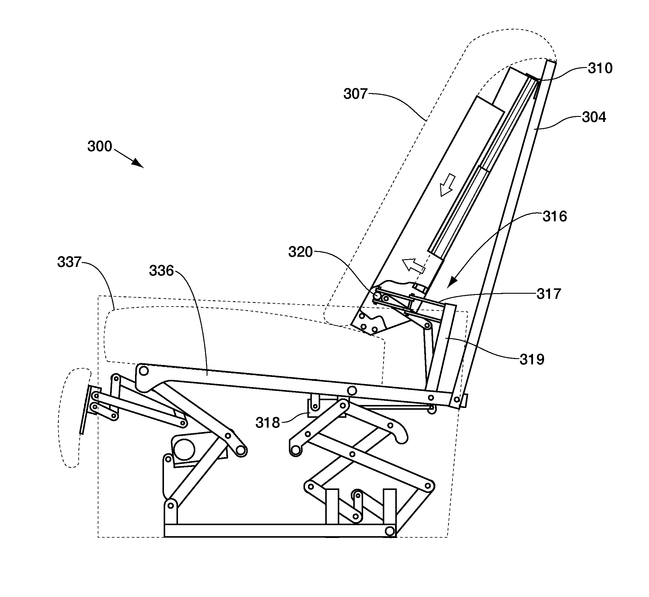
[0163]Having described the primary components of the chair 300, it should be understood that this disclosure contemplates the independent use of each of the at least five actuators (backrest 316, recline 356, footrest 390, and seat 354, 355), and that such independent use provides the chair 300 of this third embodiment with a significant ability to be reconfigured to meet the comfort or support needs of the user. In each case, the user is able to make the desired adjustments while seated so that the chair can be repeatedly adjusted for the user's comfort as their desires change during an extended period of sitting, whether watching a motion picture or receiving dialysis treatment.

[0164]The backrest actuator 316 combines with the unique features of the forward backrest frame to provide a seat depth adjustment, allowing for seating comfort for users covering a wide range of heights. This seat depth adjustment capability, as described with the first two embodiments, is the result of mo...


PUM


Abstract

A seating device such as a chair or sofa. The seating device includes a frame, a seat platform supported by the frame, and a backrest attached to the seat platform. The seat platform has opposite front and rear ends. The backrest has a first backrest portion extending upwardly from proximate the rear end of the seat platform. A lower end of the first backrest portion is positioned adjacent to an upper surface of the seat platform. The first backrest portion is capable of being moved forwardly and rearwardly along the upper surface of the seat platform while the lower end remains proximate the upper surface of the seat platform. A backrest-adjustment powered actuator operates the backrest for moving at least the first backrest portion forwardly and rearwardly partially along the upper surface of the seat platform to adjust an effective depth of the seat platform.

Description

CROSS-REFERENCE TO RELATED APPLICATION[0001]The present application is a continuation-in-part of U.S. patent application Ser. No. 13 / 041,944, which was filed Mar. 7, 2011, which is a continuation-in-part of U.S. patent application Ser. No. 11 / 971,850, which was filed Jan. 9, 2008.INCORPORATION BY REFERENCE[0002]The entire disclosure of U.S. patent application Ser. No. 11 / 971,850, which was filed Jan. 9, 2008, is incorporated herein by reference. The entire disclosure of U.S. patent application Ser. No. 13 / 041,944, which was filed Mar. 7, 2011, is incorporated herein by reference.FIELD OF THE DISCLOSURE[0003]This disclosure relates to seating devices and, more particularly, to seating devices that may be adjusted between different configurations.BACKGROUND OF THE DISCLOSURE[0004]It is conventional for seating devices to be adjustable between different configurations. However, it is believed that conventional adjustable seating devices are lacking in some regards. Accordingly, there i...

Claims


Application Information

Patent Timeline
IPC IPC(8): A47C1/032A47C7/50A47C3/20A47C3/00
CPCA47C1/03211A47C7/506A47C3/20A47C3/00A47C1/022A47C1/0242A47C1/0345A47C1/0347A47C7/024A47C7/402A47C7/405A47C7/54
Inventor HOY, DAVID E.EDMUNDS, BRIAN H.MARTELL, JR., VERNON C.
Owner GOLDILOCKS ASSOC LLC
Why Eureka
Try Eureka