
Method and apparatus for implementing a multi-dimensional optical circuit switching fabric

a multi-dimensional optical circuit and switching fabric technology, applied in multiplex communication, optical elements, instruments, etc., can solve the problems of high redundancy of switches and cables, inability to meet the characteristics of today's global data center network traffic, and limited bandwidth to the remote areas

Inactive Publication Date: 2016-05-03
LIU GUOHUA
View PDF24 Cites 15 Cited by
  • Summary
  • Abstract
  • Description
  • Claims
  • Application Information

AI Technical Summary

Benefits of technology

This solution reduces costs, improves scalability and reliability, and supports high-performance interconnection of numerous network nodes, effectively addressing the limitations of existing architectures by providing efficient bandwidth allocation and flexible routing in data centers of all sizes.

Problems solved by technology

The conventional over-subscribed tree-like architectures of data center networks provide abundant network bandwidth to the local areas of the hierarchical tree, but provide scarce bandwidth to the remote areas.
For this reason, such conventional architectures are unsuitable for the characteristics of today's global data center network traffic.
These systems use highly redundant switches and cables to achieve high network throughput.
However, these designs have several key limitations.
First, the redundant switches and cables significantly increase the cost for building the network architecture.
Second, the complicated interconnections lead to high cabling complexity, making such designs infeasible in practice.
These proposals suffer from similar drawbacks.
However, the optical switching matrix or Microelectromechanical systems (MEMS) component in OSA significantly increases the cost of the proposed architecture and more importantly limits the applicability of OSA to only small or medium sized data centers.

Method used


Image

  • Method and apparatus for implementing a multi-dimensional optical circuit switching fabric
  • Method and apparatus for implementing a multi-dimensional optical circuit switching fabric
  • Method and apparatus for implementing a multi-dimensional optical circuit switching fabric

Examples


Embodiment Construction

[0024]Certain terminology is used in the following description for convenience only and is not limiting. The words “right”, “left”, “lower”, and “upper” designate directions in the drawings to which reference is made. The terminology includes the above-listed words, derivatives thereof, and words of similar import. Additionally, the words “a” and “an”, as used in the claims and in the corresponding portions of the specification, mean “at least one.”

[0025]The present invention will be described in detail with reference to the drawings. The figures and examples below are not meant to limit the scope of the present invention to a single embodiment, but other embodiments are possible by way of interchange of some or all of the described or illustrated elements. Moreover, where some of the elements of the present invention can be partially or fully implemented using known components, only portions of such known components that are necessary for an understanding of the present invention w...


PUM


Abstract

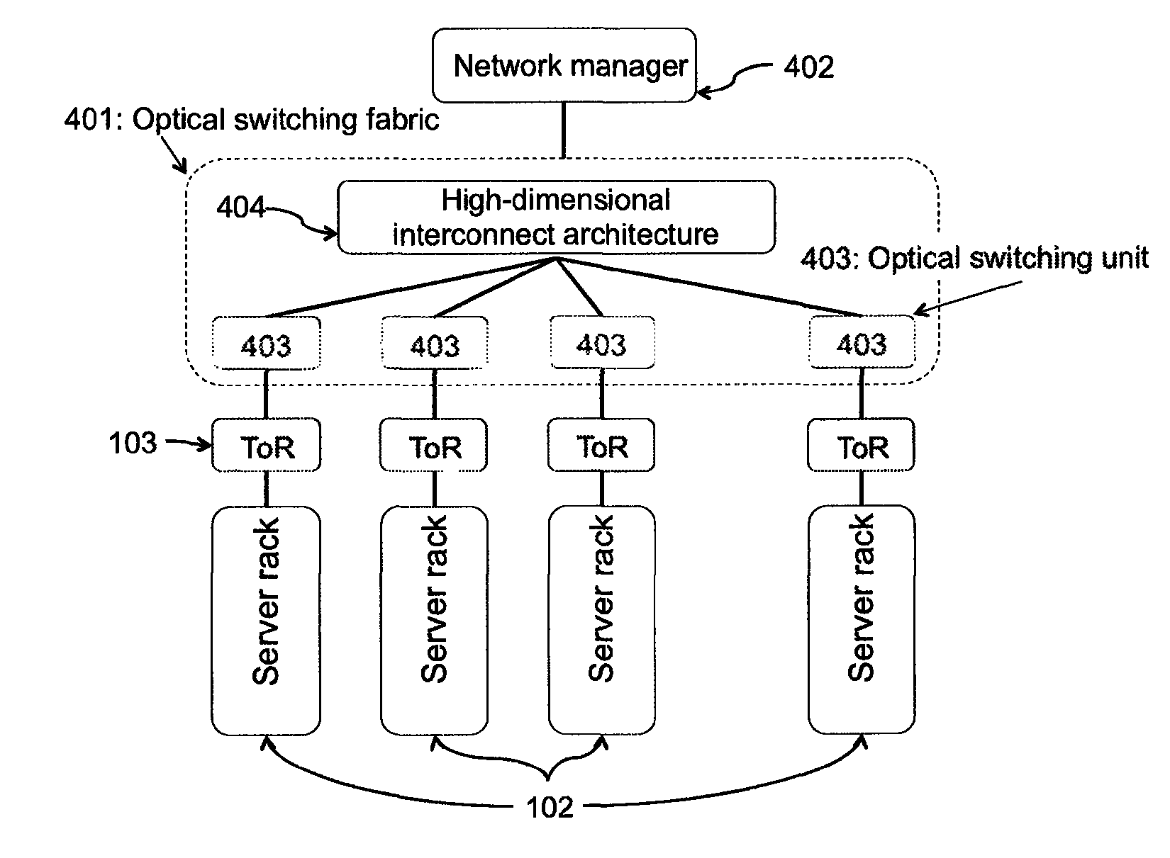
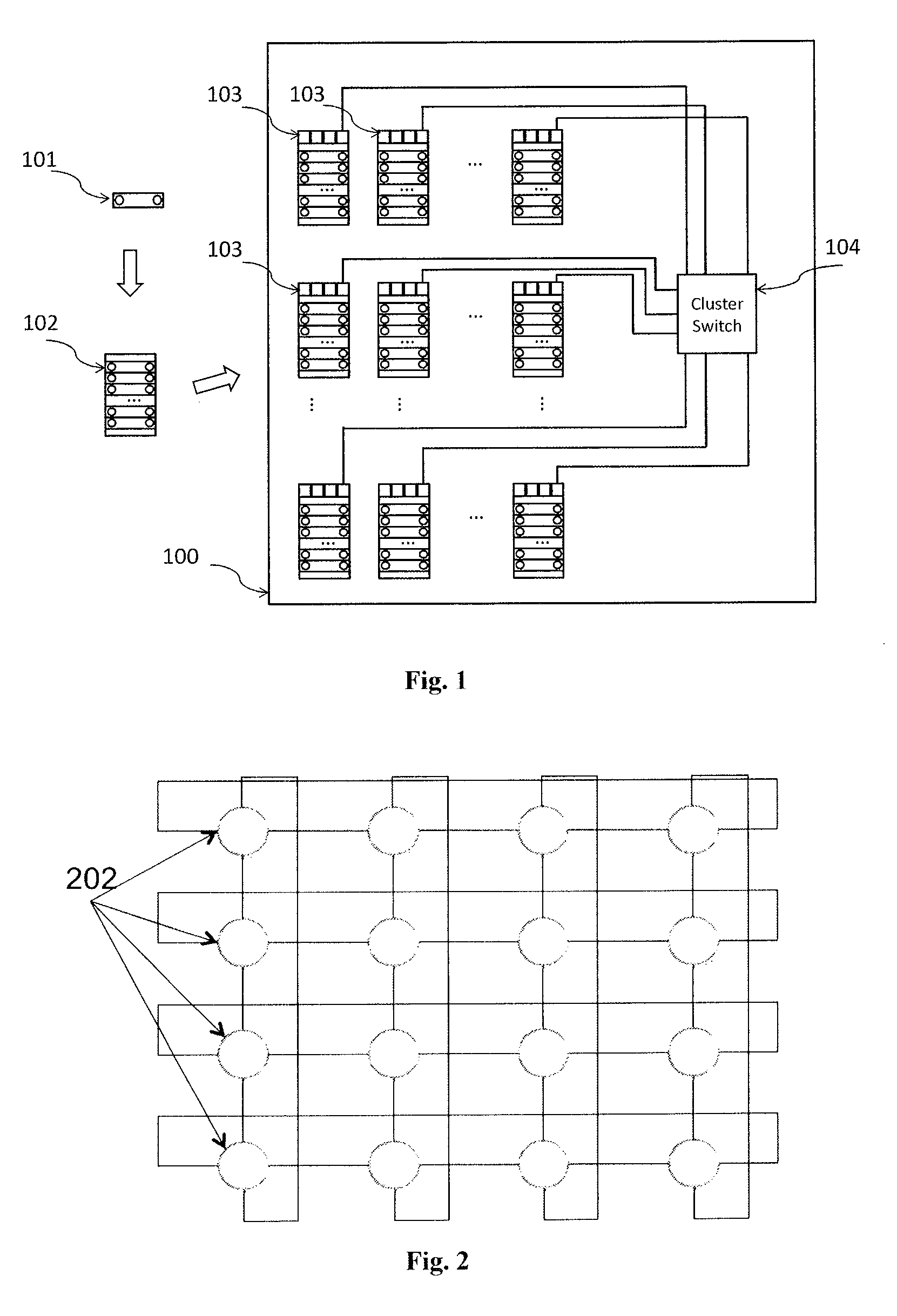
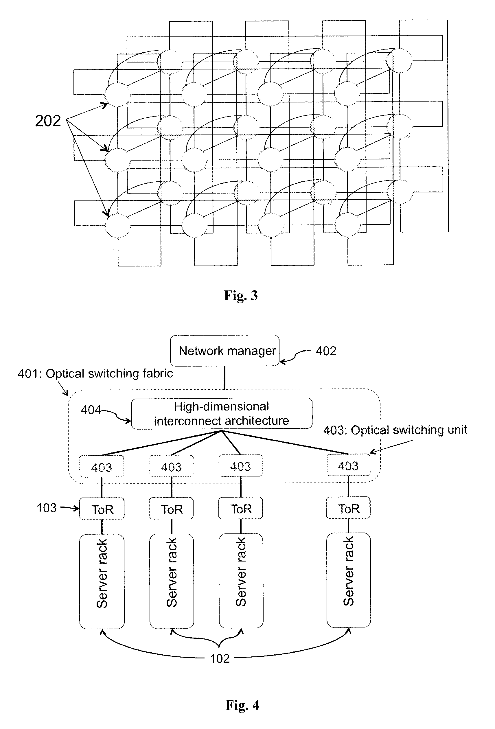
An optical switching system is described. The system includes a plurality of interconnected wavelength selective switching units. Each of the wavelength selective switching units is associated with one or more server racks. The interconnected wavelength selective switching units are arranged into a fixed structure high-dimensional interconnect architecture comprising a plurality of fixed and structured optical links. The optical links are arranged in a k-ary n-cube, ring, mesh, torus, direct binary n-cube, indirect binary n-cube, Omega network or hypercube architecture.

Description

CROSS-REFERENCE TO RELATED APPLICATIONS[0001]This application claims priority to U.S. Provisional Patent Application No. 61 / 719,026 filed Oct. 26, 2012, which is incorporated herein by reference.BACKGROUND OF THE INVENTION[0002]Embodiments of the present invention relate generally to computer network switch design and network management. More particularly, the present invention relates to scalable and self-optimizing optical circuit switching networks, and methods for managing such networks.[0003]Inside traditional data centers, network load has evolved from local traffic (i.e., intra-rack or intra-subnet communications) into global traffic (i.e., all-to-all communications). Global traffic requires high network throughput between any pair of servers. The conventional over-subscribed tree-like architectures of data center networks provide abundant network bandwidth to the local areas of the hierarchical tree, but provide scarce bandwidth to the remote areas. For this reason, such con...

Claims


Application Information

Patent Timeline
Patent Type & Authority Patents(United States)
IPC IPC(8): H04J14/00G02B6/26G02B6/42H04Q11/00G02B6/35H04J14/02
CPCH04Q11/0005G02B6/3556H04J14/0204H04J14/0205H04J14/0212H04J14/0216H04J14/0217H04Q11/0071H04Q2011/003H04Q2011/006H04Q2011/0015H04Q2011/0016H04Q2011/0035H04Q2011/0052H04Q2011/0054
Inventor ZHANG, YUEPINGXU, LEI
Owner LIU GUOHUA
Learn More