Fundus bumper mechanical reference for easier mechanism deployment

a technology of mechanical reference and bumper, which is applied in the field of intrauterine devices, can solve the problems and achieve the effect of increasing the risk of patient injury and facilitating the deployment of the devi

Active Publication Date: 2016-05-10
HOLOGIC INC
View PDF124 Cites 9 Cited by
  • Summary
  • Abstract
  • Description
  • Claims
  • Application Information

AI Technical Summary

Benefits of technology

[0005]Deployment of an intrauterine device in the uterine cavity may be a blind operation; for example, a physician may have no visual access to the uterine cavity. Typically, deployment of an intrauterine device is a multi-step, technique-sensitive task largely based on physician experience, thereby increasing the risk of injury to the patient. Accordingly, aspects and embodiments of the present disclosure are directed to providing intrauterine devices that may be deployed with ease, particularly during the seating of the device in the uterine cavity. Aspects and embodiments are also directed to providing methods for facilitating deployment of intrauterine devices within the uterine cavity.
[0019]According to another embodiment, a method for facilitating deployment of a structure including a deployment mechanism and a first central support member of an intrauterine device using a bumper configured to be at a more distal position relative to a distal end of the structure with the deployment mechanism in a collapsed state may comprise acts of advancing the structure with the deployment mechanism in the collapsed state through a cervix canal and into a uterus of a patient such that the bumper contacts a fundus of the uterus in the collapsed state; deploying the deployment mechanism from the collapsed state to a deployed state flexing away from the first central support member so that the bumper prevents the distal end of the structure from contacting the fundus during deployment of the deployment mechanism; and causing the deployment mechanism and the bumper to move relative to each other. In some embodiments, the method may further comprise an act of further advancing the structure in the deployed state so as to be closer to the fundus while the bumper maintains contact with the fundus.

Problems solved by technology

Typically, deployment of an intrauterine device is a multi-step, technique-sensitive task largely based on physician experience, thereby increasing the risk of injury to the patient.

Method used


Image

  • Fundus bumper mechanical reference for easier mechanism deployment
  • Fundus bumper mechanical reference for easier mechanism deployment
  • Fundus bumper mechanical reference for easier mechanism deployment

Examples


Embodiment Construction

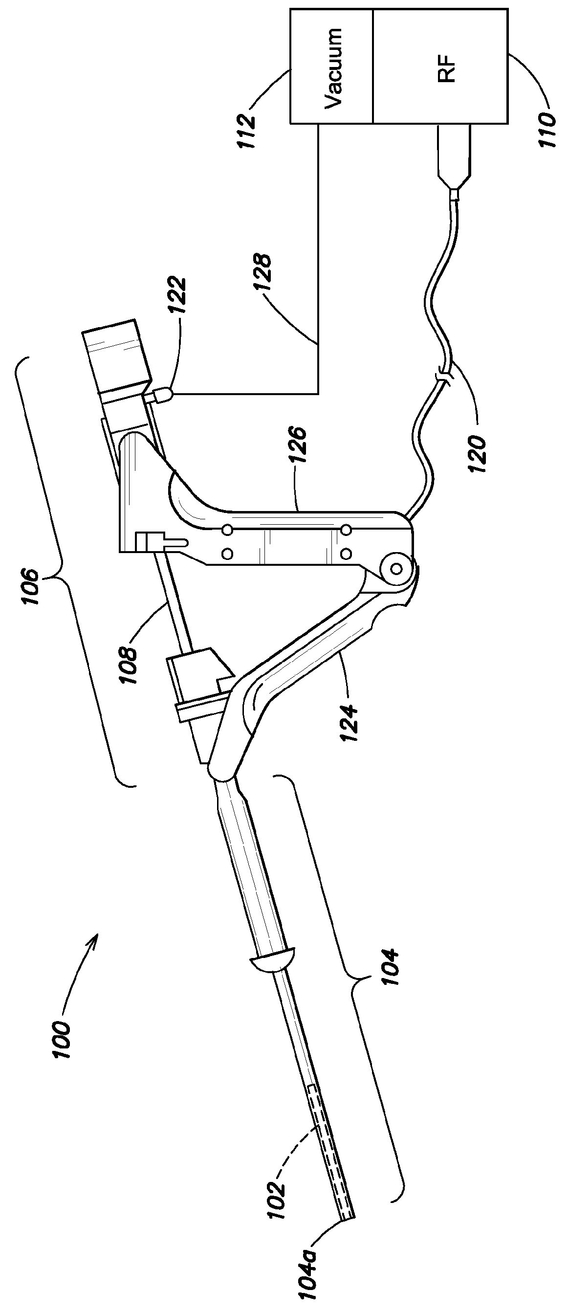
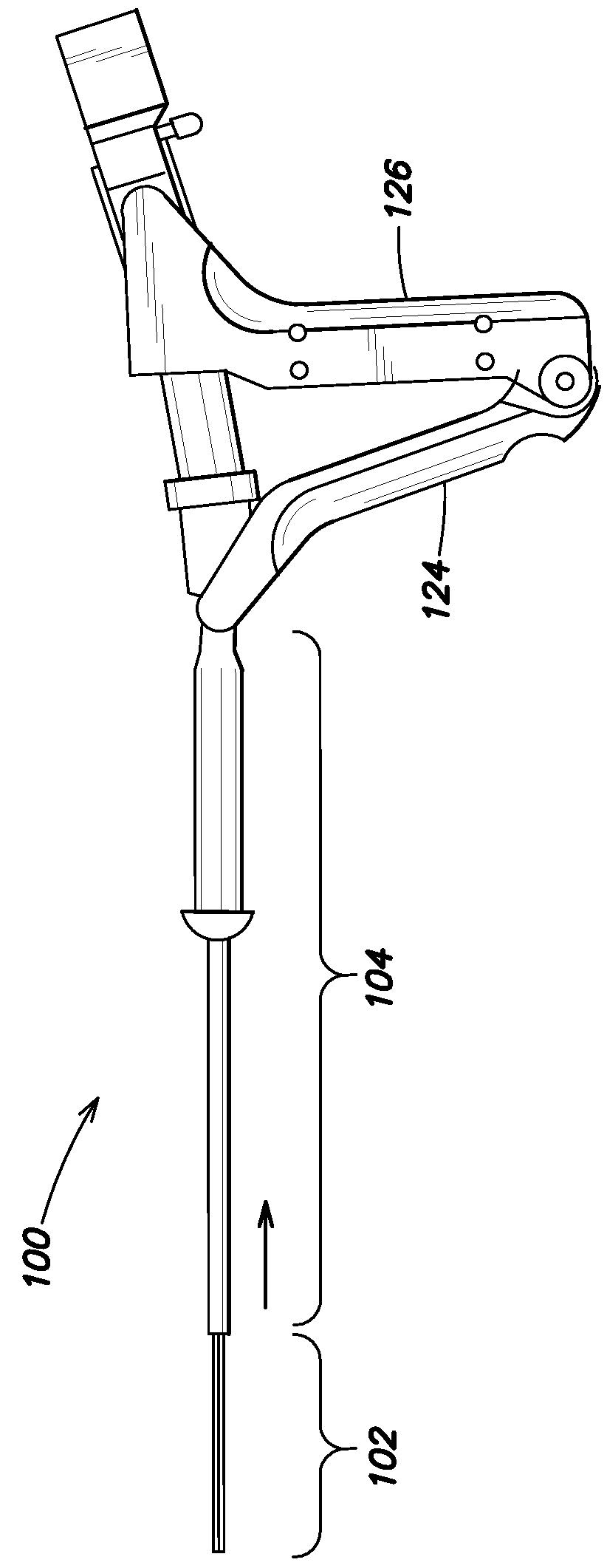
[0051]Aspects and embodiments of this disclosure are directed to providing various structures and methods for convenient and safe deployment of an intrauterine device. The intrauterine device may be an intrauterine therapy application device including a deployment mechanism that may be deployed within the uterus of a patient.

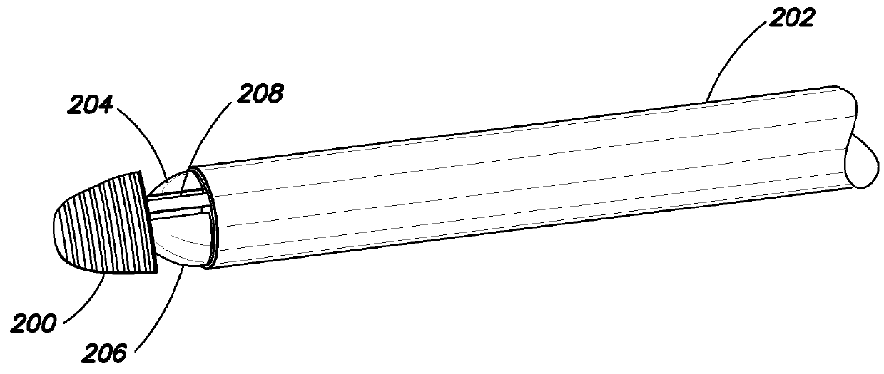
[0052]Deploying a deployment mechanism of an intrauterine device may include advancing the deployment mechanism to the fundus of the uterus and expanding the deployment mechanism by repeatedly sliding the device proximally and distally about 0.5 cm as the deployment mechanism is expanded from a collapsed position to a deployed position, lightly tapping against the fundus on each proximal stroke. Repeatedly sliding the device back and forth prevents at least a portion of the deployment mechanism, such as the tips disposed at a distal end of the deployment mechanism, from being buried in the fundus tissue while the deployment mechanism is expanding. However, this ...


PUM


Abstract

Intrauterine devices and methods for facilitating deployment thereof using a bumper are disclosed. In one embodiment, an intrauterine device comprises a structure including a first central support member and a deployment mechanism coupled to the first central support member. The intrauterine device further comprises a bumper positioned at a distal end of a second central support member and at a more distal position relative to a distal end of the structure so as to prevent the distal end of the structure from contacting the fundus of the uterus of a patient during deployment of the deployment mechanism. In another embodiment, the intrauterine device comprises a bumper coupled to the deployment mechanism and configured to move from a more distal to a more proximal position relative to a distal end of the structure.

Description

BACKGROUND[0001]1. Field of the Invention[0002]The present invention generally relates to intrauterine devices and methods of deployment thereof.[0003]2. Description of Background[0004]Intrauterine medical devices are often inserted through a patient's cervix and then expanded inside the patient's uterus. For example, a uterine ablation procedure may be performed by inserting a sheath through the cervix and then extending an applicator through the distal end of the sheath and expanding the applicator in the uterus. The applicator is expanded inside the patient, out of view of the person performing the procedure. Reliable and proper positioning and deployment of the applicator is important to avoid potential injury to the patient. Additionally, the applicator should reliably contract back into the sheath for removal from the patient.SUMMARY OF INVENTION[0005]Deployment of an intrauterine device in the uterine cavity may be a blind operation; for example, a physician may have no visua...

Claims


Application Information

Patent Timeline
Patent Type & Authority Patents(United States)
IPC IPC(8): A61B18/14A61F6/18A61B17/02A61B18/00A61B17/42
CPCA61F6/18A61B17/0218A61B17/4241A61B18/1485A61B2017/4216A61B2018/00559A61B2018/00577A61B2018/1465A61B2090/065A61B2090/08021A61B17/42A61B2018/00065A61B2018/00071A61B2018/00214
Inventor KOCHEM, THOMAS C.BEAUDET, DANIEL A.
Owner HOLOGIC INC
Why Eureka
Try Eureka