Grille and bonnet assembly for a vehicle

a technology for grilles and bonnets, which is applied in the direction of roofs, pedestrian/occupant safety arrangements, vehicular safety arrangements, etc., can solve the problems of increasing the risk of pedestrian injury, and achieve the effect of reducing the deformation capability of the bonnet, increasing the risk of pedestrian injury, and high resistance to deformation

Active Publication Date: 2007-10-11
VOLVO CAR CORP
View PDF8 Cites 5 Cited by
  • Summary
  • Abstract
  • Description
  • Claims
  • Application Information

AI Technical Summary

Benefits of technology

[0005] A vehicle is usually provided with a grille and a bonnet which are arranged adjacent to each other during normal operation when the bonnet is closed. The leading edge of the bonnet is usually arranged above or on the upper edge of the grille. During an impact where a pedestrian for instance hits the bonnet, the grille counteracts vertical movement of the bonnet since the grille normally has a relatively high resistance to deformation when being loaded in the vertical direction. This implies that the deformation capability of the bonnet is strongly reduced in the area close to the grille. In most cases the mass-moment of inertia of the bonnet, and the force exerted by any other component supporting the bonnet, creates a sufficient resistance against movement of the bonnet to cushion the impact. Any additional resistance against movement or resistance to deformation caused by a grille could increase the risk of injury to the pedestrian.
[0007] It is an object of this invention to provide a grille and bonnet assembly for a vehicle of the kind referred to in the introduction, by which grille and bonnet assembly the risk of injury to a pedestrian during an impact between the pedestrian and a vehicle is reduced to a substantial extent.
[0010] By the provision of a grille and bonnet assembly where the grille portion and the bonnet portion are designed and located relative to each other such that above a predetermined value representative of a force to be transmitted from the bonnet portion to the grille portion, the bonnet portion is arranged to force at least the upper part of the grille portion to move forwardly, the bonnet portion can move downwardly during an impact while the resistance against movement caused by the grille is reduced or substantially eliminated.
[0011] It is an advantage of this invention that the grille and bonnet assembly according to the instant invention can be used for achieving a pedestrian protection in an accident between a vehicle and a pedestrian. In particular, possibly head injuries of a child caused by a collision can be reduced.
[0013] It is yet another object of this invention to provide a grille and bonnet assembly for an automotive vehicle that is arranged to yield during impact to allow the downward movement of the bonnet, and which is durable in construction, inexpensive of manufacture, carefree of maintenance, facile in assemblage, and simple and effective in use.
[0014] These and other objects, features and advantages are accomplished according to the instant invention by providing a grille and bonnet assembly is mounted at the forward end of an automotive vehicle. The bonnet is formed with a leading edge and a trailing edge with the leading edge positioned above or at an upper edge of the grille during normal operation of the automotive vehicle when the bonnet is closed. The grille and bonnet are designed with corresponding inclined surfaces that are located relative to each other such that a force greater than a predetermined value transmitted from the bonnet to the grille forces at least the upper part of the grille to move forwardly so as to allow the bonnet to move downwardly. Such yielding movement of the grille and bonnet can reduce injuries in the event of an impact between a pedestrian and the bonnet of the automotive vehicle.

Problems solved by technology

Any additional resistance against movement or resistance to deformation caused by a grille could increase the risk of injury to the pedestrian.

Method used


Image

  • Grille and bonnet assembly for a vehicle
  • Grille and bonnet assembly for a vehicle
  • Grille and bonnet assembly for a vehicle

Examples


Embodiment Construction

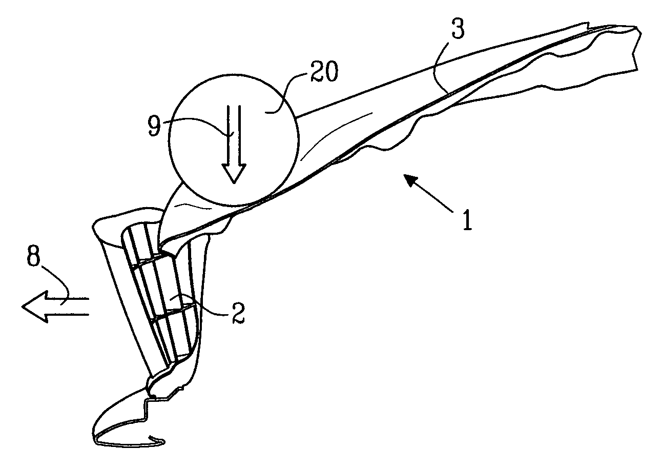
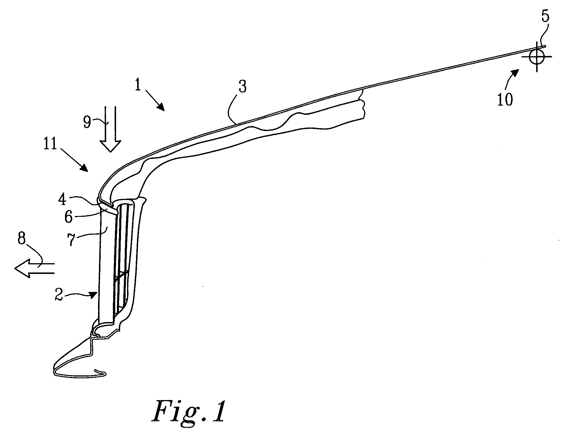
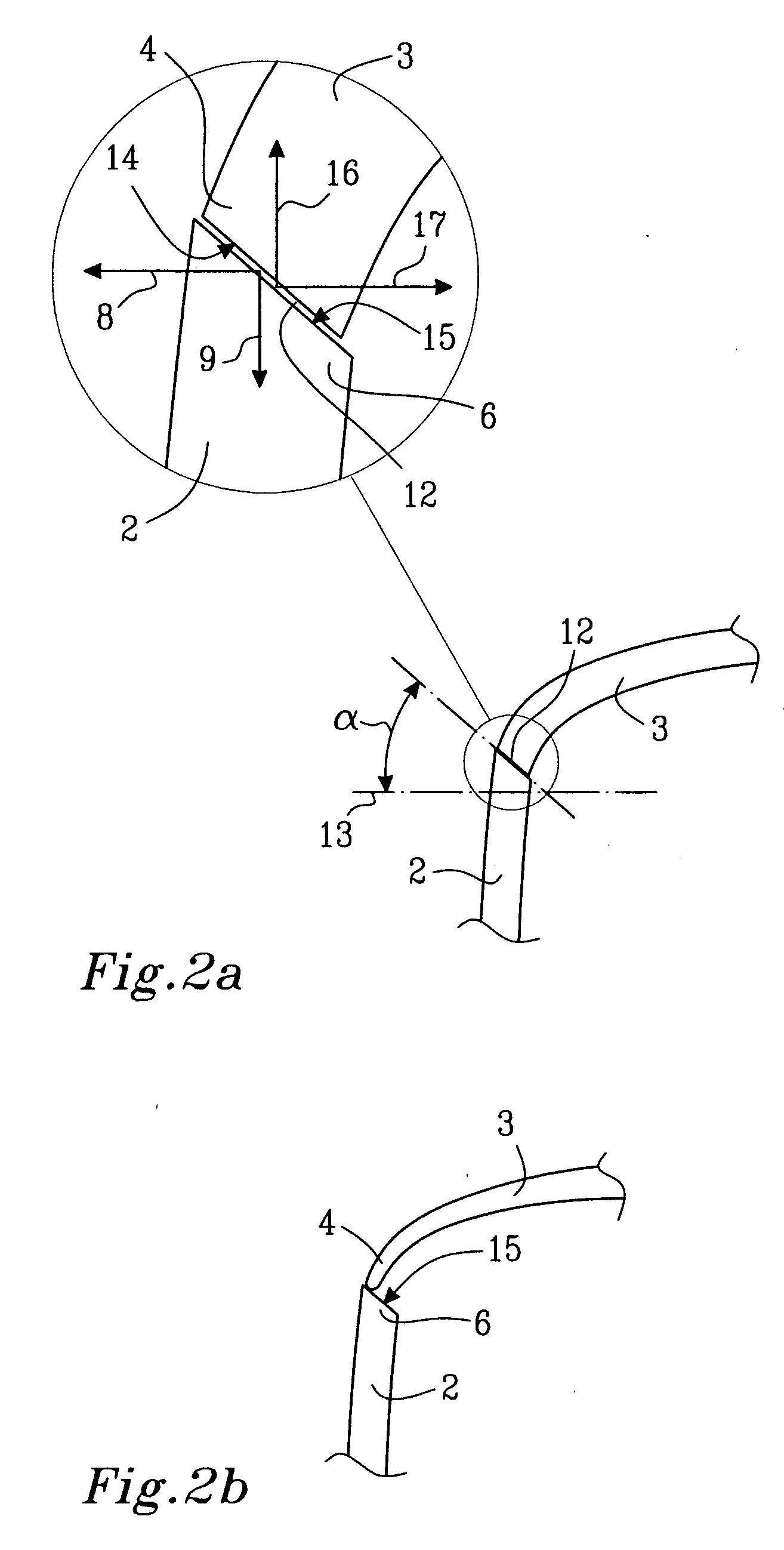
[0022] Referring now to FIGS. 1-3c, a grille and bonnet assembly 1 for an automotive vehicle incorporating the principles of the instant invention can best be seen. The grille and bonnet assembly 1 for a vehicle comprises a grille portion 2 and a bonnet portion 3. The bonnet portion 3 has a leading edge 4 and a trailing edge 5 and the leading edge 4 is arranged above or on an upper edge 6 of the grille portion 2 during normal operation when the bonnet is closed. As best seen in FIGS. 2a and 2b, the leading edge 4 of the bonnet portion and the upper edge 6 of the grille portion 2 at least partly overlap each other when viewed in a vertical direction.

[0023] The grille portion 2 and the bonnet portion 3 are designed and located relative to each other such that above a predetermined value representative of a force to be transmitted from the bonnet portion 3 to the grille portion 2, the bonnet portion 3 is arranged to force at least the upper part 7 of the grille portion 2 to move forwa...


PUM


Abstract

A grille and bonnet assembly is mounted at the forward end of an automotive vehicle. The bonnet is formed with a leading edge and a trailing edge with the leading edge positioned above or at an upper edge of the grille during normal operation of the automotive vehicle when the bonnet is closed. The grille and bonnet are designed with corresponding inclined surfaces that are located relative to each other such that a force greater than a predetermined value transmitted from the bonnet to the grille forces at least the upper part of the grille to move forwardly so as to allow the bonnet to move downwardly. Such yielding movement of the grille and bonnet can reduce injuries in the event of an impact between a pedestrian and the bonnet of the automotive vehicle.

Description

FIELD OF THE INVENTION [0001] The invention relates to a grille and bonnet assembly for an automotive vehicle, and, more particularly, to a mounting mechanism that moves the grille forwardly to allow the bonnet to move downwardly when incurring an impact. BACKGROUND OF THE INVENTION [0002] Motor vehicle manufacturers are constantly striving to provide vehicles which, in the event of a collision, reduce the risk of injury to persons involved in the collision. These persons may be occupants of the vehicle or a pedestrian which is struck by the vehicle. To this end, vehicles are nowadays designed with so-called deformation zones which deform in a controlled manner to thereby absorb energy which arises during impact between the vehicle and an object. The amount of energy which arises in a collision is proportional to the square of the relative velocity between the vehicle and the object at impact. Accordingly, the risk of injury to occupants of vehicles is increased at higher speeds. Du...

Claims


Application Information

Patent Timeline
Patent Type & Authority Applications(United States)
IPC IPC(8): B62D25/10B60R21/34B60R21/38
CPCB60R2019/525B60R21/38
Inventor WALLMAN, MATTIASOLSSON, LENNARTFREDRIKSSON, ANDERS
Owner VOLVO CAR CORP
Why Eureka
Try Eureka