Radio-enabled collision avoidance system

a collision avoidance and radio-enabled technology, applied in the field of radio sensors, can solve the problems of requiring significant re-working, requiring intensive and often variable signal processing, and requiring laser, radar, camera-based instrumentation arrays for the sensing system used on vehicles

Inactive Publication Date: 2016-05-17
BAE SYST INFORMATION & ELECTRONICS SYST INTEGRATION INC
View PDF21 Cites 5 Cited by
  • Summary
  • Abstract
  • Description
  • Claims
  • Application Information

AI Technical Summary

Benefits of technology

[0011]Applicants believe the invention is novel in at least two areas: (1) the use of radios to target or exclude regions of the environment from the operating space of a semi-autonomous controller; and (2) the use of a semi-autonomous controller (rather than a simple warning system, emergency-stop, or full-fledged autonomous controller) to assist the operator in avoiding hazards.
[0012]Advantages to the present invention include the ability to operate at FCC-regulated power levels in RFID bands. These power levels are lower than levels required for radars. Other advantages include the ability to mark non-metallic obstacles and the ability to specifically identify obstacles based on modulated RFID tag returns.

Problems solved by technology

In the majority of applications today, sensing systems that are used on vehicles require an expensive array of laser, radar, and camera-based instrumentation.
The combination of these components requires intensive and often variable signal processing in order to estimate the position of hazards in the environment.
Even if such sensing systems were technically and financially feasible for manufacturers and end users, they would require significant re-working to allow operators to mark certain regions of the environment as being unsafe.
It should come as no surprise that in many job sites, trying to separate one region of the environment from another based on color, hue, or roughness alone would be wildly insufficient.
For example, in the case where a wall of a building is to be removed while another wall (similar in color, texture, and size) is to remain untouched, onboard sensors would struggle to differentiate the two walls and appropriately apply the constraints.

Method used


Image

  • Radio-enabled collision avoidance system
  • Radio-enabled collision avoidance system
  • Radio-enabled collision avoidance system

Examples


Embodiment Construction

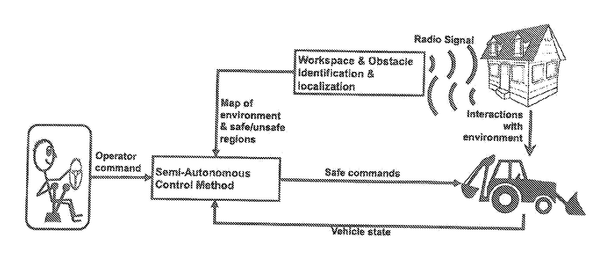
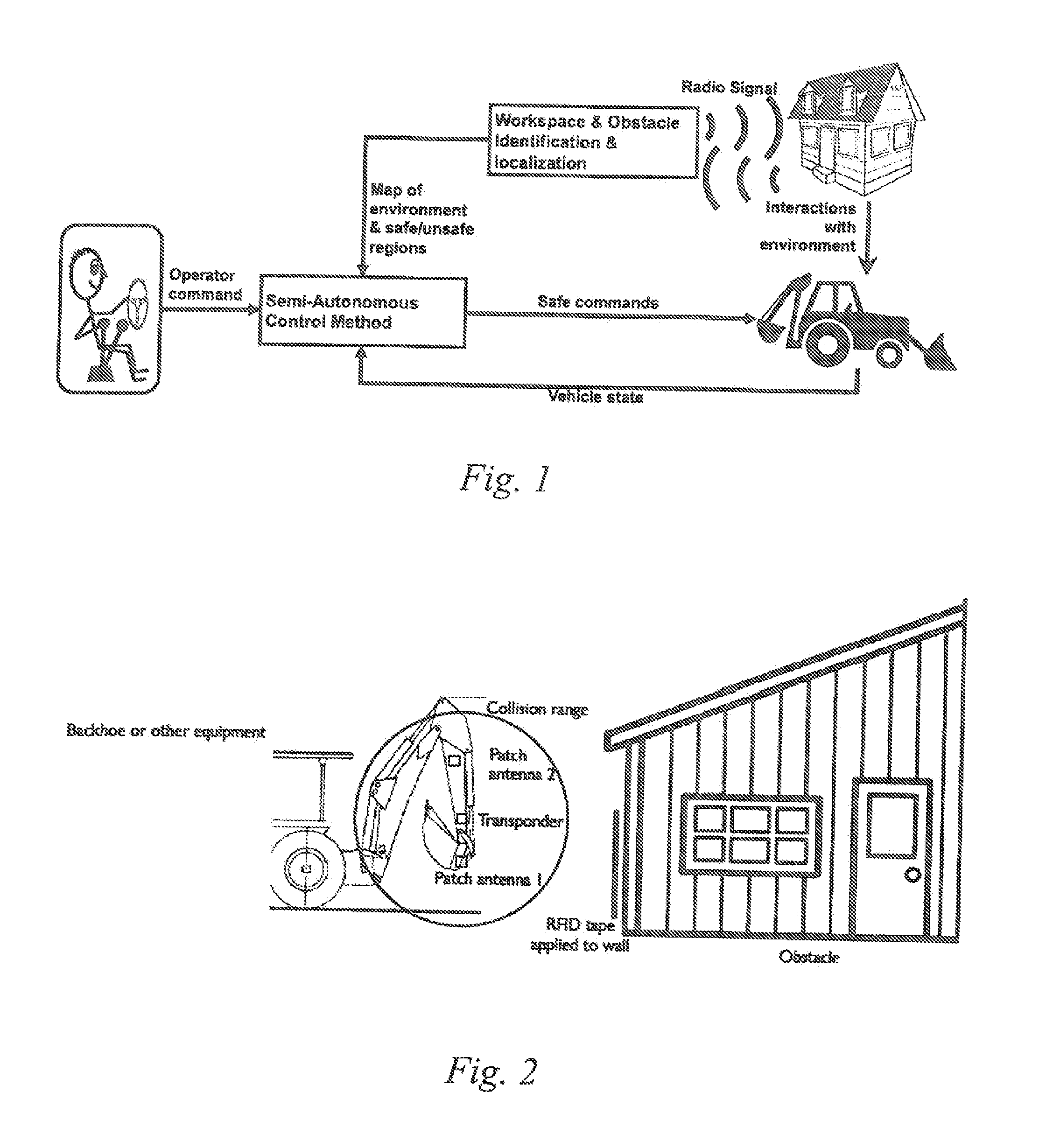
[0030]The method and apparatus disclosed herein provide a fast, inexpensive, and robust means of preventing unintended collisions between a human-controlled machine (e.g., forklift, excavator, medical instrument, industrial manipulator, etc.) and hazardous or impassible regions of the environment (warehouse shelving, gas piping, unintended organs, pedestrians, etc.). FIG. 1 shows a block diagram for this system as applied to a scenario in which an excavator performs work near a house. In this case, regions of the house that should not be hit might be tagged beforehand with radio tape, and any gas pipelines near the workspace might be marked with radio emitters. The controller onboard the excavator then reads in the radio signal, designs constraints based on the position of radio emitters, and ensures that neither the excavator tool (e.g., backhoe, jackhammer, etc.) nor the excavator vehicle itself (e.g., tractor body) collides with the house or pipeline. Note that in this system, th...


PUM


Abstract

In the method of reducing the likelihood of collisions, the improvement comprising the step of embedding passive radio transponders in a tape, grease, or other materials; applying said passive radio transponders to an object of which collisions must be avoided, and mounting an active interrogating transponder on a moving machinery, which uses the information provided by the radio transponders to semi-autonomously avoid collisions.

Description

CROSS REFERENCE TO RELATED APPLICATION[0001]This application claims rights under 35 U.S.C. 119(e) from Application Ser. No. 61 / 666,315 filed Jun. 29, 2012, the contents of which are incorporated herein by reference.FIELD OF THE INVENTION[0002]The present invention relates to radio sensors and methods for using them and the information they provide to systematically help avoid collisions between machinery and obstacles / pedestrians.BRIEF DESCRIPTION OF PRIOR DEVELOPMENTS[0003]In the majority of applications today, sensing systems that are used on vehicles require an expensive array of laser, radar, and camera-based instrumentation. The combination of these components requires intensive and often variable signal processing in order to estimate the position of hazards in the environment. Even if such sensing systems were technically and financially feasible for manufacturers and end users, they would require significant re-working to allow operators to mark certain regions of the enviro...

Claims


Application Information

Patent Timeline
Patent Type & Authority Patents(United States)
IPC IPC(8): G08G9/02G01S13/93G01S13/75B60W30/095G01S13/931
CPCG08G9/02G01S13/75G01S13/931B60W30/095
Inventor BROMMER, KARL D.ANDERSON, STERLING J.BROMMER, DIETER B.IAGNEMMA, KARL D.
Owner BAE SYST INFORMATION & ELECTRONICS SYST INTEGRATION INC
Why Eureka
Try Eureka