Automatic display of remote camera image

a technology of remote camera and image, which is applied in the field of automatic display of remote camera image, can solve the problems of becoming more difficult for the combine operator to maintain visual contact with the functions of harvesting process and logistics

Active Publication Date: 2016-05-24
BLUE LEAF I P INC
View PDF38 Cites 23 Cited by
  • Summary
  • Abstract
  • Description
  • Claims
  • Application Information

AI Technical Summary

Problems solved by technology

As combine harvesters (“combines”) become larger and more complicated, it becomes more difficult for the combine operator to maintain visual contact with functions of the harvesting process and logistics of operating and maneuvering the combine harvester.
However, this requires the combine operator to determine which images to see and to select them, all the while operating an increasingly complicated machine.

Method used


Image

  • Automatic display of remote camera image
  • Automatic display of remote camera image
  • Automatic display of remote camera image

Examples


example 1

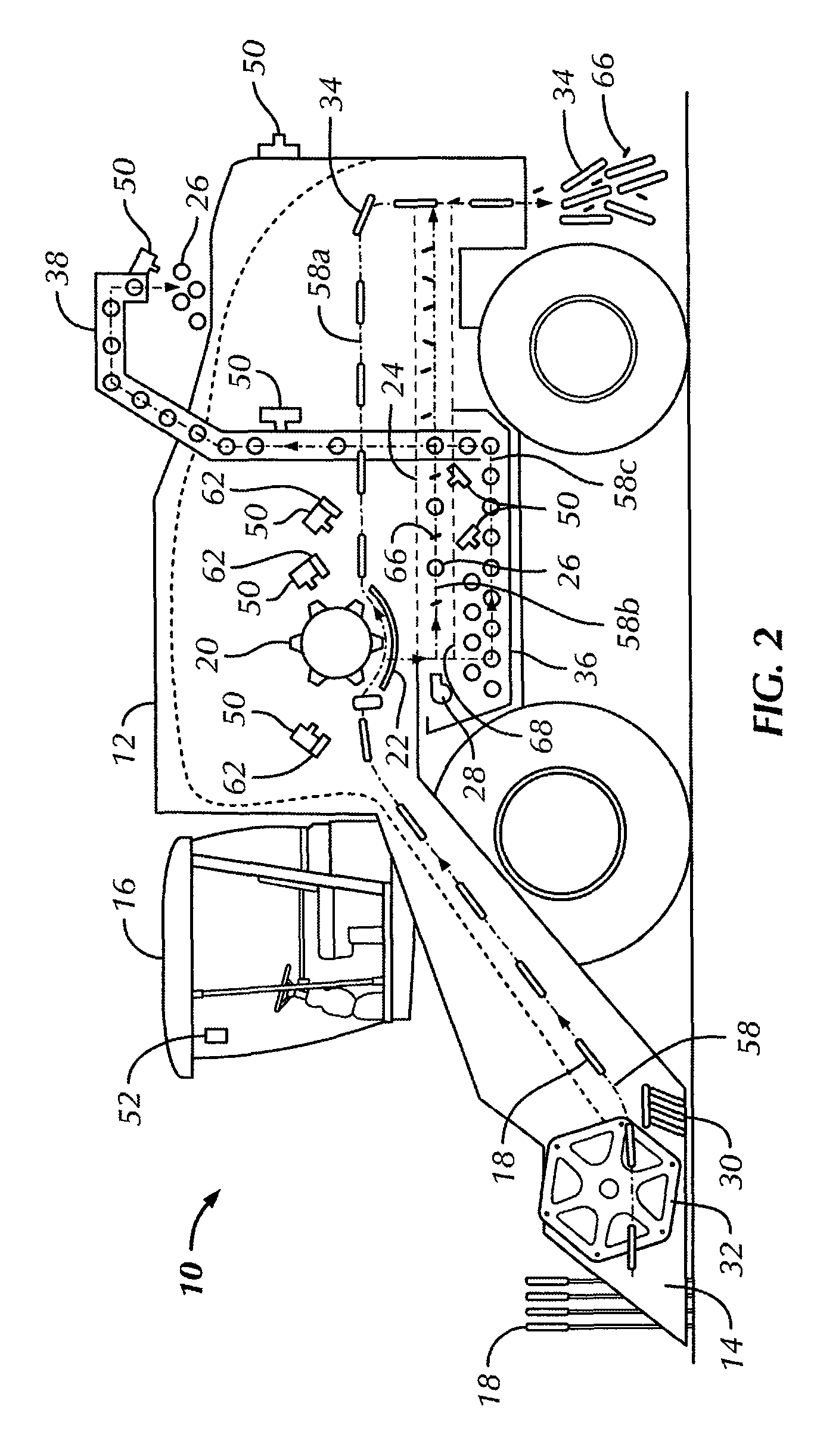
[0041]1) Structure: A combine harvester includes a video camera 50 facing the discharge end of unloading tube 38. The video camera 50 is directly connected to the graphic display 52. The video camera 50 is always on.

[0042]2) Programming: If the unloading tube 38 is activated (e.g. its auger / conveyor is activated, or it is moved to a discharge position), the processor 60 will display the images of the video camera 50 which is facing the unloading tube 38.

[0043]3) Steps:

[0044]A) Operator presses a switch, enters a command or otherwise signals a desire to activate the unloading tube 38.

[0045]B) The electronic operator module 48 detects this event in A) and broadcasts a message on the vehicle data bus 40 indicating that the unloading tube 38 has been activated.

[0046]C) The control modules 42 receive the message from B), and the chassis control module 70 responds by turning on the electrical drive to the unloader auger 72 to move grain through the unloading tube 38.

[0047]D) The graphic d...

example 2

[0048]1) Structure: A combine harvester has a video camera 50 facing the sieves 24. The video camera 50 is directly connected to the graphic display 52. The video camera 50 is always on. The light source 62 is an electric light and is off until activated.

[0049]2) Programming: If the concave clearance control is activated, the graphic display control module 44 will automatically instruct the graphic display 52 to display the images of the video camera 50 which is facing the sieves 24 and the control module 42 will automatically instruct the light source 62 which illuminates the sieves 24 inside the farm vehicle 10 to turn on. The light source 62 may be on continuously, for a predetermined length of time, or for a variable length of time which corresponds to the display of images of the video camera 50 which is facing the sieves 24 on the graphic display 52.

[0050]3) Steps:

[0051]A) Operator presses a switch, enters a command or otherwise signals a desire to change the concave clearance...

example 3

[0056]1) Structure: The structure is the same as in Example 2, except that the video camera 50 is connected to the graphic display 52 via the graphic display control module 44.

[0057]2) Programming: Same as Example 2, except that the graphic display control module 44 will transmit the images to be displayed by the graphic display 52, rather than instructing the graphic display 52 which images to display.

[0058]3) Steps:

[0059]A) Same as Example 2.

[0060]B) Same as Example 2.

[0061]C) Same as Example 2.

[0062]D) The graphic display control module 44 detects the message from B) and responds to it by sending to the graphic display 52 image data from the video camera 50 which faces the sieves 24 for display.

[0063]E) Same as Example 2.


PUM


Abstract

A farm vehicle includes a crop gathering mechanism to convey harvested crop material to a crop flow path passing internally through at least part of the vehicle. The vehicle includes a vehicle data bus and a plurality of control modules operatively connected to the vehicle data bus and configured to monitor information on the vehicle data bus and to act according to such information. An electronic operator module is configured to monitor the states of operator controls and to broadcast information on the vehicle data bus specifying such states. Additionally, video cameras positioned within the vehicle face the crop flow path and are operably connected to a graphic display. A graphic display control module includes a processor configured to control the display of images on the graphic display for selective display of images from the video cameras based upon information from the vehicle data bus.

Description

BACKGROUND OF THE INVENTION[0001]As combine harvesters (“combines”) become larger and more complicated, it becomes more difficult for the combine operator to maintain visual contact with functions of the harvesting process and logistics of operating and maneuvering the combine harvester. To that end, remote mounted video cameras may be utilized on combine harvesters to allow the operator to ‘see’ critical functions. For example, the images may be displayed on a dedicated video monitor in the combine cab and the vehicle control monitor can have the ability to show video output if the operator manually selects to view the desired video footage.[0002]Some of the functions that may be viewed via a remote mounted video camera are the unloading process, and backing up of the combine while driving the combine in reverse. A camera mounted either to the end of the unloading tube directed into the receiving receptacle or cameras mounted at the rear of the combine used to view the combine surr...

Claims


Application Information

Patent Timeline
Patent Type & Authority Patents(United States)
IPC IPC(8): A01D41/127H04N7/18A01F12/00
CPCA01D41/127
Inventor SCHROEDER, JAY DAVIDRENAUD, DANIEL LYNNKING, JOHN MICHAELMCKEE, KEVIN DOUGLAS
Owner BLUE LEAF I P INC
Why Eureka
Try Eureka