Fuel tank

Active Publication Date: 2016-05-24
AISAN IND CO LTD
View PDF19 Cites 2 Cited by
  • Summary
  • Abstract
  • Description
  • Claims
  • Application Information

AI Technical Summary

Benefits of technology

The invention makes it easier to connect the parts of a vehicle's engine to the engine's fuel tank. This reduces the space where fuel vapor can accumulate and reduces the amount of fuel vapor that is generated. The canister, which helps trap fuel vapor, is placed in the tank, so the amount of fuel stored is not reduced.

Problems solved by technology

Therefore, even in case where only the canister is to be detached and attached afterward, detaching and attaching of the canister is not possible.
Furthermore, it is difficult for the canister to be separately subjected to a product inspection.

Method used


Image

  • Fuel tank
  • Fuel tank
  • Fuel tank

Examples


first embodiment

Summary of Fuel Tank 10

[0025]Hereinafter, a fuel tank according to a first embodiment of the present invention will be described with respect to FIGS. 1 to 8. The fuel tank according to this embodiment is a fuel tank with a canister to be used in a vehicle.

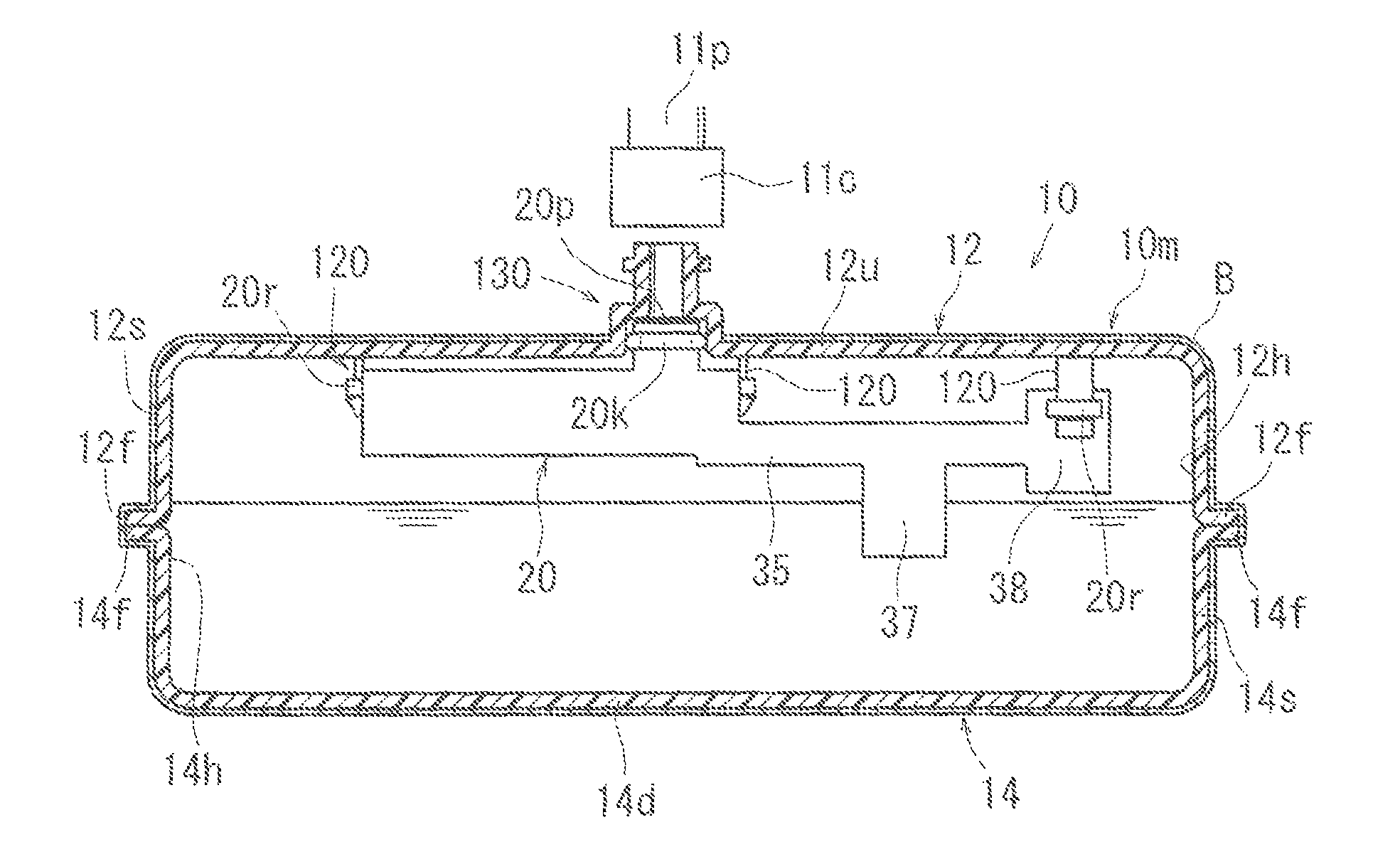
[0026]The fuel tank 10 includes a tank body 10m constituted by an upper shell 12 and a lower shell 14 as illustrated in FIG. 2 and the like. The upper shell 12 and the lower shell 14 are resin injection-molded products, and the surfaces thereof are covered with a barrier layer B having fuel permeation resistance. Here, as a resin that is a body material of the upper shell 12 and the lower shell 14, for example, high-density polyethylene (HDPE) is used, and as a material of the barrier layer B, and ethylene vinyl alcohol copolymer (EVOH) is used.

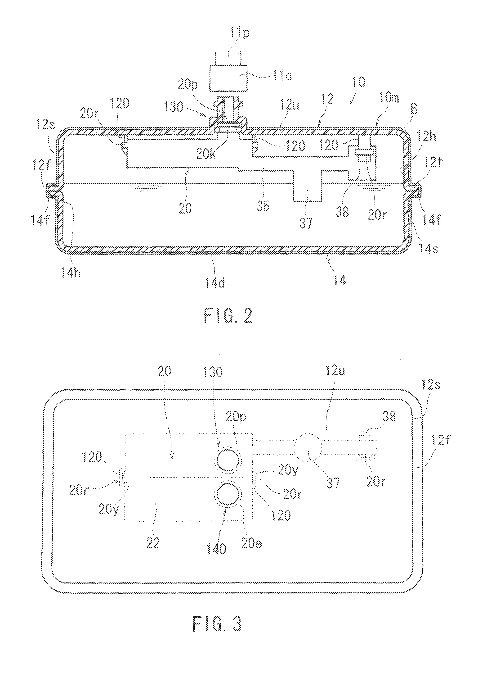
[0027]The upper shell 12 is formed by an upper plate portion 12u and a side plate portion 12s in a square container shape in which the lower side thereof is opened, and a flange portion 12f...

modification example

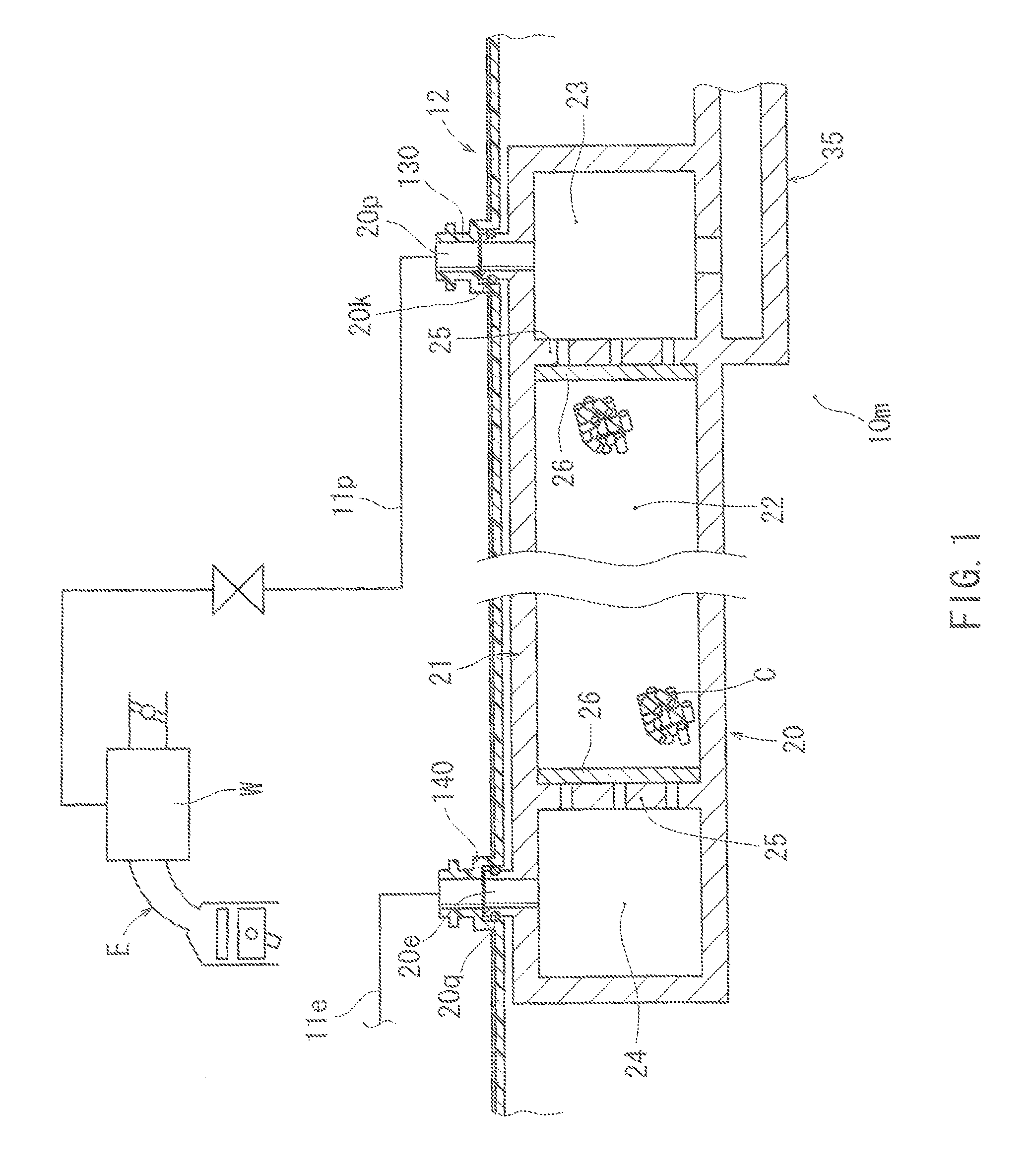
[0056]Here, the present invention is not limited to the above-described embodiment, and may be modified in a scope that does not depart from the gist of the present invention. For example, in this embodiment, an example in which the fill-up regulating valve 37 is provided at the intermediate position of the vapor pipe 35 and the cut-off valve 38 is provided at the tip position of the vapor pipe 35, the fuel vapor in the tank body 10m is introduced into the vapor pipe 35 via the fill-up regulating valve 37 or the cut-off valve 38 and is guided into the first sub-chamber 23 of the canister 20 by the vapor pipe 35 is illustrated.

[0057]However, as illustrated in FIG. 5, a configuration in which the fill-up regulating valve 37 is omitted and a bidirectional check valve 30 is provided in an inlet portion of the first sub-chamber 23 of the canister 20 is possible. Here, the bidirectional check valve 30 is a protection valve that prevents damage of tank body 10m and is typically held in a c...


PUM


Abstract

The present invention enables a canister in a fuel tank with the canister to be separately subjected to a product inspection and enables the canister to be replaced.The fuel tank according to the present invention includes: a tank body (10m) configured by joining a plurality of shells (12) and (14) to each other; and a canister (20) configured to enable absorption of fuel vapor generated in the tank body (10m), wherein, in one (12) of the shells that constitute the tank body (10m), and engaging portion (120) formed to be integral with the shell (12) is provided, and the canister (20) is configured to be mounted to the tank body (10m) by engaging an engaged portion (20r) of the canister (20) with the engaging portion (120).

Description

TECHNICAL FIELD[0001]The present invention relates to a fuel tank which includes a task body configured by joining a plurality of shells to each other, and a canister configured to enable adsorption of fuel vapor generated is the tank body.BACKGROUND ART[0002]A technique related to the fuel tank described above is disclosed in JP-A-2008-168767.[0003]The tank body of the fuel tank is constituted by an upper shell and a lower shell, which are made of an injection-molded resin. The container body of the canister is formed to be integrated with the inner wall surface of the upper shell when the upper shell is injection-molded. The container body of the canister is filled with an adsorbent such as activated carbon, and an opening of the container body is closed by a cover material. Next, a flange portion of the upper shell and a flange portion of the lower shell are joined to each other, thereby completing the tank body.[0004]In the fuel tank described above, when the upper shell include...

Claims


Application Information

Patent Timeline
IPC IPC(8): F02M37/20F02M25/08B60K15/03B60K15/035F17D1/00
CPCF02M25/0854B60K15/03177B60K15/03504F02M25/089B60K2015/03467B60K2015/03514
Inventor KIMOTO, JUNYA
Owner AISAN IND CO LTD
Why Eureka
Try Eureka