Scroll fluid machine with axial sealing unit

a fluid machine and sealing unit technology, applied in the direction of machines/engines, rotary/oscillating piston pump components, liquid fuel engines, etc., can solve the problems of bearing grease deterioration, bearing damage, time-consuming and laborious bearing grease replenishmen

Inactive Publication Date: 2016-05-31
ANEST IWATA CORP
View PDF19 Cites 3 Cited by
  • Summary
  • Abstract
  • Description
  • Claims
  • Application Information

AI Technical Summary

Benefits of technology

[0014]Furthermore, when, in a double wrap type scroll fluid machine such as that disclosed in Patent Document 2, the revolving wrap is supported and restricted in the axial direction using a tip seal, the revolving wrap and the fixed wrap come into contact so as to interfere with each other as wear on the tip seal progresses. The tip seal must therefore be replaced before becoming worn to the extent that such contact and interference occur. As a result, an operating time of the scroll fluid machine is reduced by being dependent on a working life of the tip seal.
[0032]According to the present invention, a scroll fluid machine in which a pin crank mechanism is not provided in a compression chamber, thereby eliminating the need to provide a bearing in the compression chamber and enabling an increase in a continuous operating time of the scroll fluid machine, can be provided.

Problems solved by technology

The pin crank mechanism requires a bearing, and therefore, in a scroll fluid machine in which the pin crank mechanism exists in the compression chamber, foreign matter adhered to bearing grease and corrosive gas may cause the bearing grease to deteriorate and the bearing to be damaged.
Further, to replenish the bearing grease, the compression chamber of the scroll fluid machine must be dismantled, and therefore bearing grease replenishment is time-consuming and laborious.
Moreover, it is necessary either to lubricate the bearing using grease or to employ a dry bearing as the bearing, and in both cases, costs relating to the bearing increase.
Furthermore, when, in a double wrap type scroll fluid machine such as that disclosed in Patent Document 2, the revolving wrap is supported and restricted in the axial direction using a tip seal, the revolving wrap and the fixed wrap come into contact so as to interfere with each other as wear on the tip seal progresses.
However, when the axial direction is supported by a bearing, the bearing must be increased in size and provided with a complicated structure such as that of an angular contact ball bearing so that the bearing can bear a load, and as a result, the bearing cannot easily be disposed in the compression chamber.
However, when the vacuum seal technique disclosed in Patent Document 3 is applied, the P seal is a contact type seal and therefore becomes worn.

Method used


Image

  • Scroll fluid machine with axial sealing unit
  • Scroll fluid machine with axial sealing unit
  • Scroll fluid machine with axial sealing unit

Examples


first embodiment

[0039

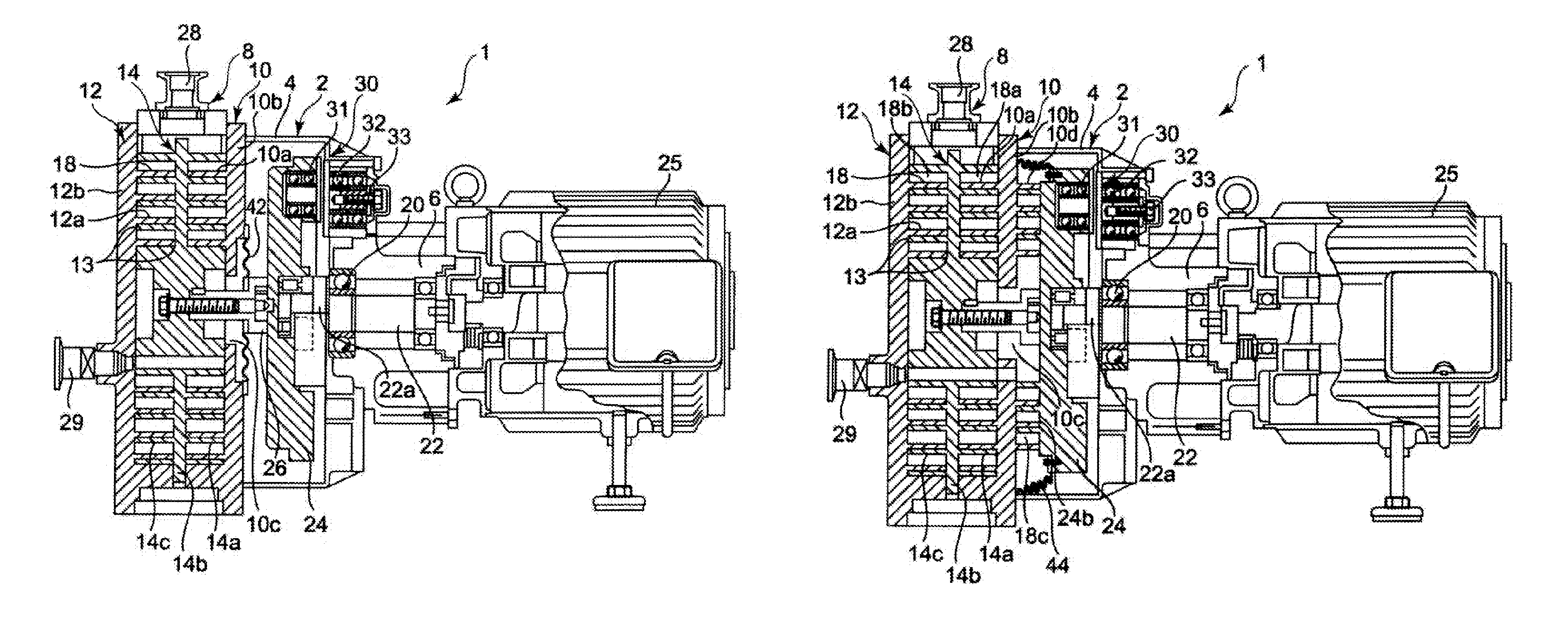
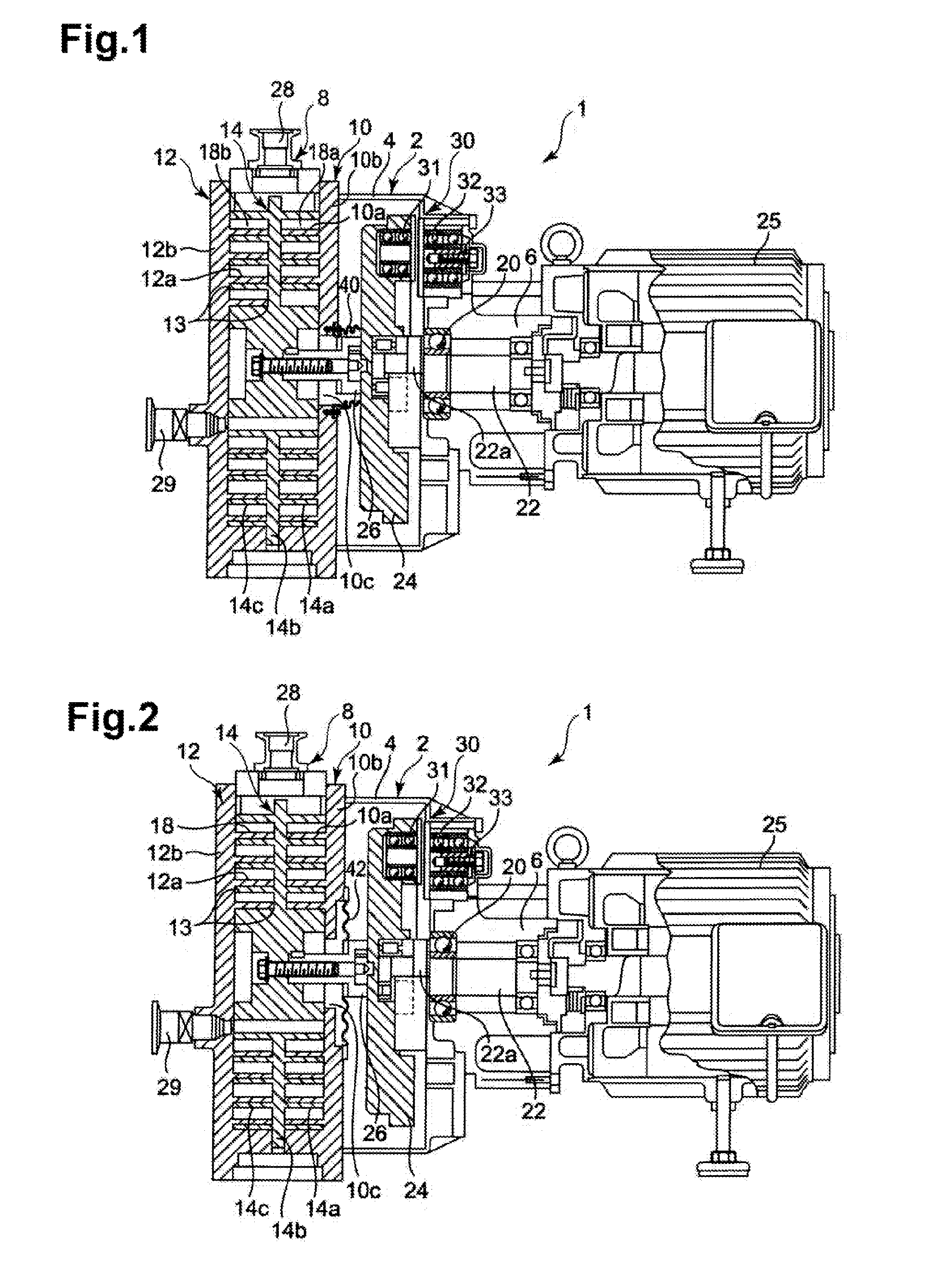
[0040]FIG. 1 is a side view showing a partial cross-section of a scroll fluid machine according to a first embodiment.

[0041]First, a configuration of a scroll fluid machine according to the first embodiment will be described on the basis of FIG. 1.

[0042]In a scroll fluid machine 1 shown in FIG. 1, 2 denotes a compressor casing forming an outer frame of the scroll fluid machine 1. The compressor casing 2 is schematically constituted by a casing main body 4 that is open on one side, and a tubular bearing portion 6 formed to project toward an opposite side to the opening in the casing main body 4.

[0043]A compression portion 8 forms a main body of the scroll fluid machine 1 and is schematically constituted by a fixed scroll 10 that is attached to the casing main body 4 by a back surface thereof and includes a plurality of fixed wraps 10a standing upright on a front surface thereof, a fixed scroll 12 that is provided opposite the fixed scroll 10 and includes a fixed wrap 12a standin...

second embodiment

[0059

[0060]FIG. 2 is a side view showing a partial cross-section of a scroll fluid machine according to a second embodiment.

[0061]In FIG. 2, identical reference symbols to FIG. 1 represent identical objects, and description thereof has been omitted.

[0062]In FIG. 2, a bellows 42 is provided in place of the bellows 40 shown in FIG. 1. The bellows 42 is provided over the entire periphery of the boss 26 to connect the rear surface (the surface opposing the revolving disc 24) of the fixed scroll 10 to the boss 26. The compression portion 8 can likewise be sealed in the axial direction by providing the bellows 42 in the manner shown in FIG. 2.

[0063]According to the second embodiment, in addition to similar effects to the first embodiment, a distance between the fixed scroll 10 and the revolving disc 24 can be shortened, enabling a further increase in the overall compactness of the scroll fluid machine 1.

third embodiment

[0064

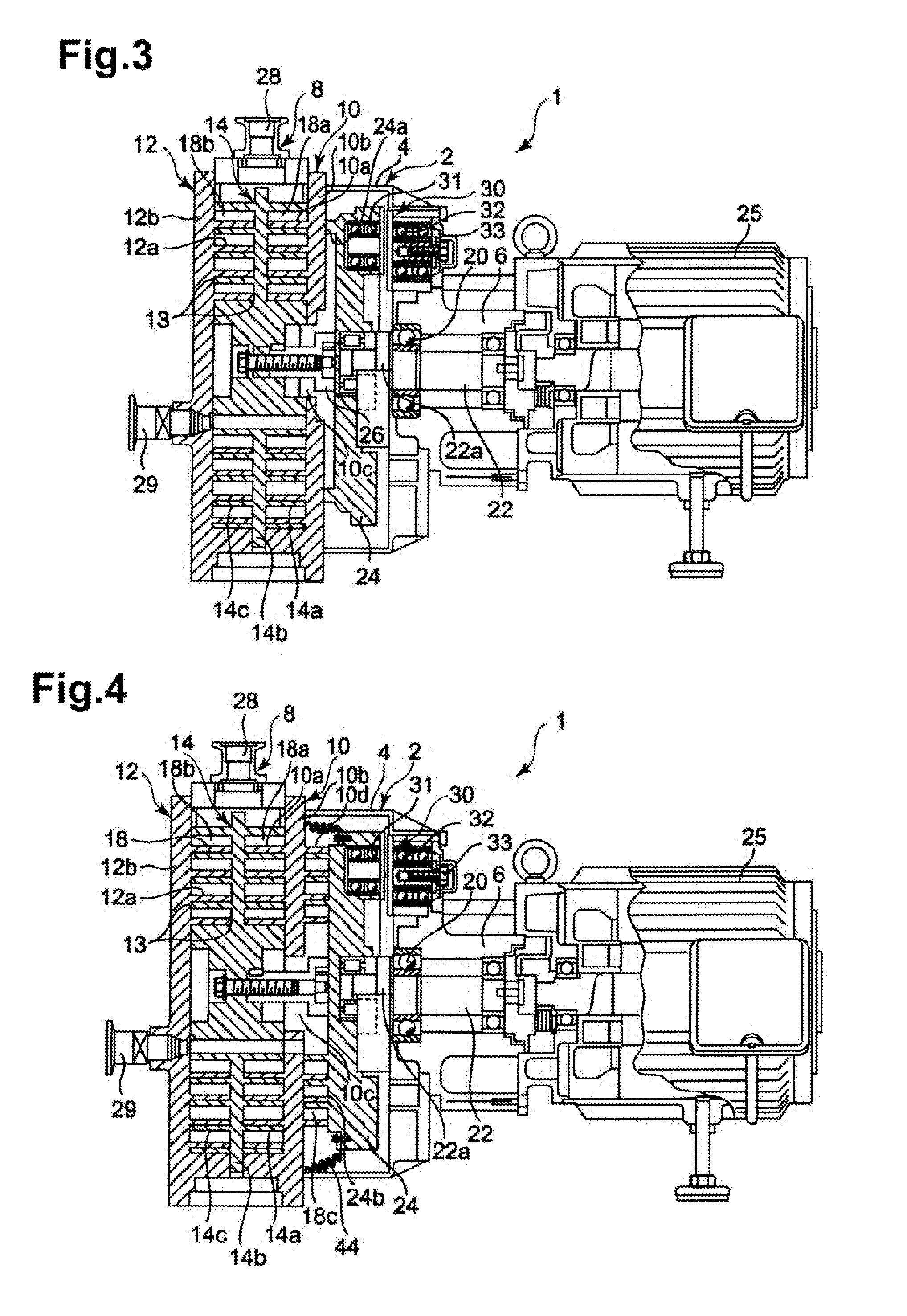
[0065]FIG. 3 is a side view showing a partial cross-section of a scroll fluid machine according to a third embodiment.

[0066]In FIG. 3, identical reference symbols to FIG. 1 or FIG. 2 represent identical objects, and description thereof has been omitted.

[0067]In FIG. 3, the bellows 40 shown in FIG. 1 and the bellows 42 shown in FIG. 2 are not provided.

[0068]Instead, a ring-shaped projecting portion 24a is provided on the surface of the revolving disc 24 that opposes the fixed scroll 10. The projecting portion 24a is provided so as to surround the boss 26 and configured such that a tip end thereof contacts the surface of the fixed scroll 10 that opposes the revolving disc, whereby the tip end slides over the surface of the fixed scroll 10 as the revolving disc 24 revolves. As a result, the compression portion 8 can be sealed in the axial direction by the projecting portion 24a.

[0069]According to the third embodiment, in addition to similar effects to the first embodiment, a bell...


PUM


Abstract

A scroll fluid machine includes a revolving scroll in which a revolving wrap stands upright on an end plate supported revolvably on a drive shaft, and a fixed scroll which is provided opposite the revolving scroll and in which a fixed wrap stands upright on an end plate. The revolving and fixed wraps overlap to form a compression chamber for compressing a fluid by causing the revolving scroll to revolve. The scroll fluid machine further includes a rod-shaped member attached to the end plate of the revolving scroll and extending to a rear surface side of the fixed scroll, which is a side not opposing the revolving scroll. A revolving plate is attached to the rod-shaped member, provided with a pin crank mechanism, and supported revolvably on the drive shaft. The revolving plate is provided with a sealing unit that seals the compression chamber in an axial direction.

Description

RELATED APPLICATIONS[0001]The present application is a continuation of International Application Number PCT / JP2011 / 076848, filed Nov. 22, 2011, which claims the benefit of Japanese Application Number 2011-003323, filed Jan. 11, 2011, the disclosure of which is hereby incorporated by reference herein in its entirety.TECHNICAL FIELD[0002]The present invention relates to a scroll fluid machine, and more particularly to a scroll fluid machine in which a pin crank mechanism is not provided in a compression chamber where compression is performed, thereby eliminating the need to provide a bearing in the compression chamber with the result that damage to the bearing in the compression chamber can be avoided.BACKGROUND ART[0003]A scroll fluid machine is known in the related art as a type of compressor used for air compression, refrigeration, and air-conditioning. A scroll fluid machine typically includes a revolving scroll having a revolving wrap that stands upright on an end plate supported...

Claims


Application Information

Patent Timeline
Patent Type & Authority Patents(United States)
IPC IPC(8): F04C18/02F04C27/00F04C23/00
CPCF04C18/0246F04C18/0223F04C18/0253F04C27/008F04C23/001F04C27/005F04C29/0057
Inventor ITO, HIROSHITANIGAWA, SHIROMIDORIKAWA, YOUHEI
Owner ANEST IWATA CORP
Why Eureka
Try Eureka