Developer supply container, developer supplying apparatus and image forming apparatus

a technology for supplying containers and image forming apparatus, which is applied in the direction of electrographic process apparatus, instruments, optics, etc., can solve the problem that the efficiency of developing the discharging of containers immediately after the use amount of the developer supply container into the image forming apparatus may be low

Active Publication Date: 2016-05-31
CANON KK
View PDF29 Cites 23 Cited by
  • Summary
  • Abstract
  • Description
  • Claims
  • Application Information

AI Technical Summary

Benefits of technology

[0005]Accordingly, it is a object of the present invention to provide a developer supply container, a developer supplying device and an image forming apparatus with which the developer can be easily discharged from the developer supply container to immediately after the use amount the developer supply container into the image forming apparatus.

Problems solved by technology

However, with the structure of Japanese Laid-open Patent Application 2010-256893, a developer discharging efficiency immediately after the use amount of the developer supply container into the image forming apparatus may be low because of the situation before the developer supply container reaches the user.

Method used


Image

  • Developer supply container, developer supplying apparatus and image forming apparatus
  • Developer supply container, developer supplying apparatus and image forming apparatus
  • Developer supply container, developer supplying apparatus and image forming apparatus

Examples


embodiment 1

[0025]First, basic structures of an image forming apparatus will be described, and then, a developer supplying system, that is, a developer replenishing apparatus and a supply container used in the image forming apparatus will be described.

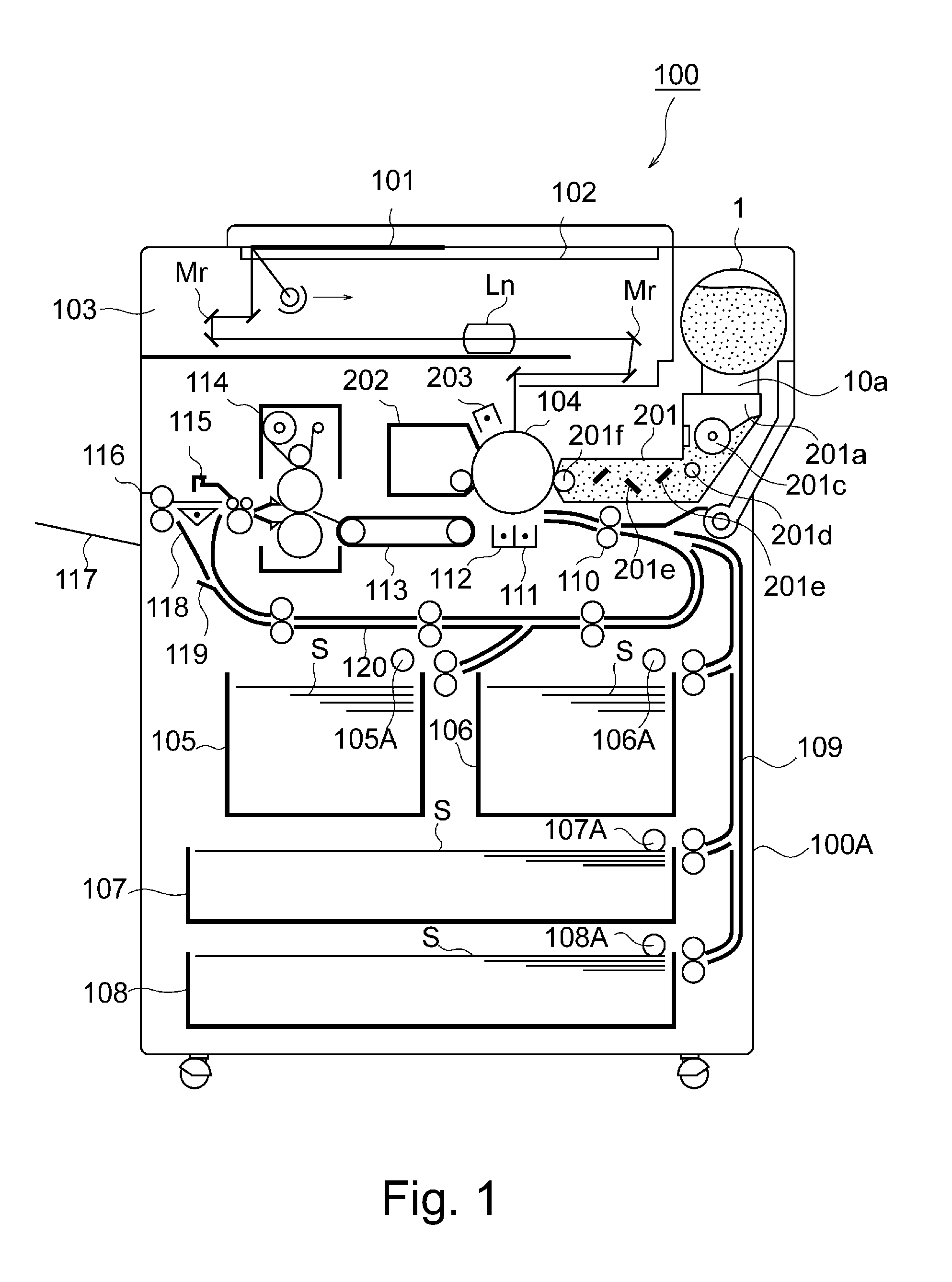
(Image Forming Apparatus)

[0026]FIG. 1 is a sectional view of an image forming apparatus 100 according to Embodiment 1 The image forming apparatus 100 is an example of an electrophotographic type copying machine (electrophotographic image forming apparatus) and is provided with a supplying device 201 to which a supply container 1 (so-called toner cartridge) is detachably mountable (demountable). The supply container 1 as the “developer supply container” is detachably mountable to the supplying device 201 as “developer supplying apparatus”, that is, detachably mountable to a main assembly 100A of the image forming apparatus. Therefore, when the supply container 1 and / or the supplying device 201 is in the form of a cartridge, the cartridge is detacha...

embodiment 2

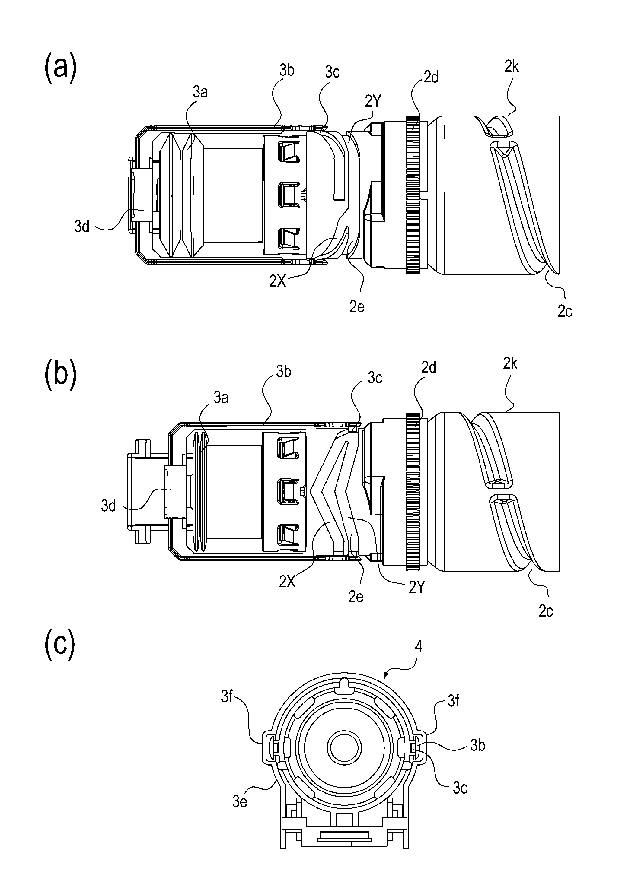
[0173]Referring to FIG. 16, Embodiment 2 will be described. FIG. 16 is a development of cam grooves 2X, 2Y in Embodiment 2. As will be understood from FIG. 16, the cam grooves 2X, 2Y a different from those of Embodiment 1. The other structures are the same as those of Embodiment 1. In the description of this embodiment, the same reference numerals as in Embodiment 1 are assigned to the elements having the corresponding functions in this embodiment, and the detailed description thereof is omitted for simplicity.

[0174]As shown in FIG. 16, the difference of this embodiment from Embodiment 1 is in that an amplitude K1 (expansion and contraction length of the pump portion 3a) in the expansion and contracting directions B, C of the pump portion 3a provided by the first cam groove 2X is small.

[0175]More particularly, in this embodiment, the driving force converting portion includes a first cam groove 2X which is formed on and which extends in the rotational moving direction of the supply c...


PUM


Abstract

A developer supply container, the developer supply container includes a developer accommodating chamber; a rotatable feeding portion; a developer discharging chamber including a discharge opening; a driving force receiving portion for receiving a rotational force for rotating the feeding portion; an pump capable of changing an inside volume of the accommodating chamber in a longitudinal direction of the container to apply a pressure to the discharge opening; a driving force converter for converting the rotational force into a feeding driving force for feeding the developer by an operation of the pump in a longitudinal direction of the container; and wherein an expansion and contraction stroke of the pump provided by the converter in a initial predetermined number of rotations in a initial stage is different from that in a subsequent stage after the initial stage.

Description

FIELD OF THE INVENTION AND RELATED ART[0001]The present invention relates to a developer supply container detachably mountable to a developer supplying device and also relates to the developer supplying apparatus and an image forming apparatus using the same. The developer supplying apparatus is used with an image forming apparatus such as a copying machine, a facsimile machine, a printer or a complex machine having functions of a plurality of such machines.[0002]Conventionally, an image forming apparatus such as an electrophotographic copying machine uses a developer of fine particles. In such an image forming apparatus, the developer is supplied from a supply container (developer supply container) in response to consumption thereof resulting from image forming operation. Such a supply container is disclosed in Japanese Laid-open Patent Application 2010-256893, for example.[0003]The apparatus disclosed in Japanese Laid-open Patent Application 2010-256893 employs a system in which t...

Claims


Application Information

Patent Timeline
Patent Type & Authority Patents(United States)
IPC IPC(8): G03G15/00G03G15/08
CPCG03G15/0865G03G15/0872G03G15/0877
Inventor OKINO, AYATOMONAGASHIMA, TOSHIAKIMURAKAMI, KATSUYATAZAWA, FUMIO
Owner CANON KK
Why Eureka
Try Eureka