
Method and equipment for measuring the filter sectors in disc filters

a technology of disc filters and filter sectors, which is applied in the direction of measuring wheels, instruments, separation processes, etc., can solve the problems of clogging of the surface of lime sludge layers, affecting the operation of the disc filter, and limiting the filtration capacity, so as to reduce the duration of interruption in operation.

Active Publication Date: 2016-06-14
VALMET AB
View PDF17 Cites 1 Cited by
  • Summary
  • Abstract
  • Description
  • Claims
  • Application Information

AI Technical Summary

Benefits of technology

The patent describes a way to quickly measure the deflection of filters and determine which parts need adjustment. This saves time compared to manual measurements.

Problems solved by technology

Independently of whether the filters are green liquor, white liquor or lime sludge filters, it is not possible to reach the desired purity of the filtrate (green liquor, white liquor or washing fluid) without first coating the filter surface with a layer of lime sludge.
At the same time as the mesh of the cloth must be fine, it must not produce too large pressure drop, since this limits the filtration capacity.
The technique means that the layers of lime sludge will capture most of the lime sludge particles in the process fluid that is to be filtered, but it eventually leads to the surface of the layers of lime sludge becoming clogged and needing to be renewed.
One problem with these disc filters with precoating is that the pressure drop, and thus the filtration capacity, is directly dependent on the thickness of the layer of lime sludge.
The layer of lime sludge on this lower filter sector will then become thicker than on other filter sectors, and the pressure drop will for this reason be higher, which will result in a lower filtration capacity.
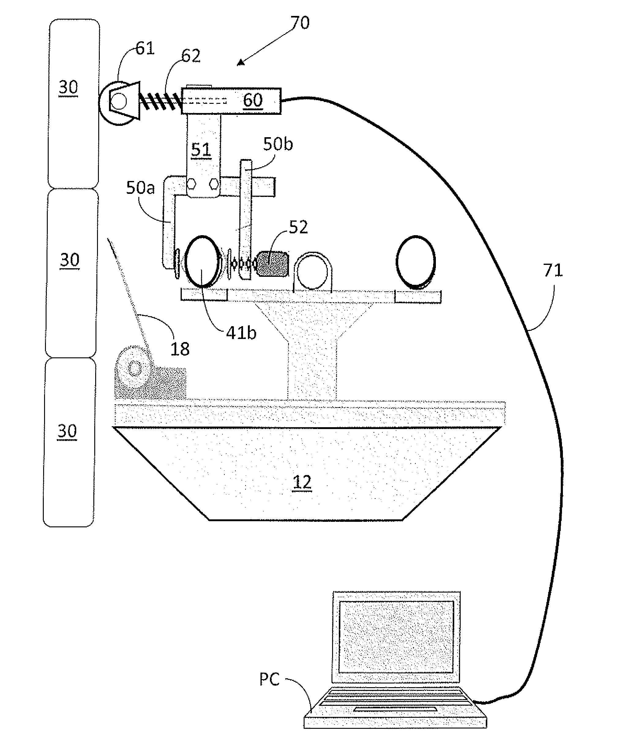
The measurement process is also associated with risks for the personnel since it is necessary to measure inside a machine with cramped space while the disc filter is rotated, and where the distance between a sharp scraper and the surface of the filter is measured using a ruler.
Since the measurement process is time-consuming, the complete production line must also be closed down during this period, and this causes a large loss of income for the paper pulp mill.

Method used


Image

  • Method and equipment for measuring the filter sectors in disc filters
  • Method and equipment for measuring the filter sectors in disc filters
  • Method and equipment for measuring the filter sectors in disc filters

Examples


Embodiment Construction

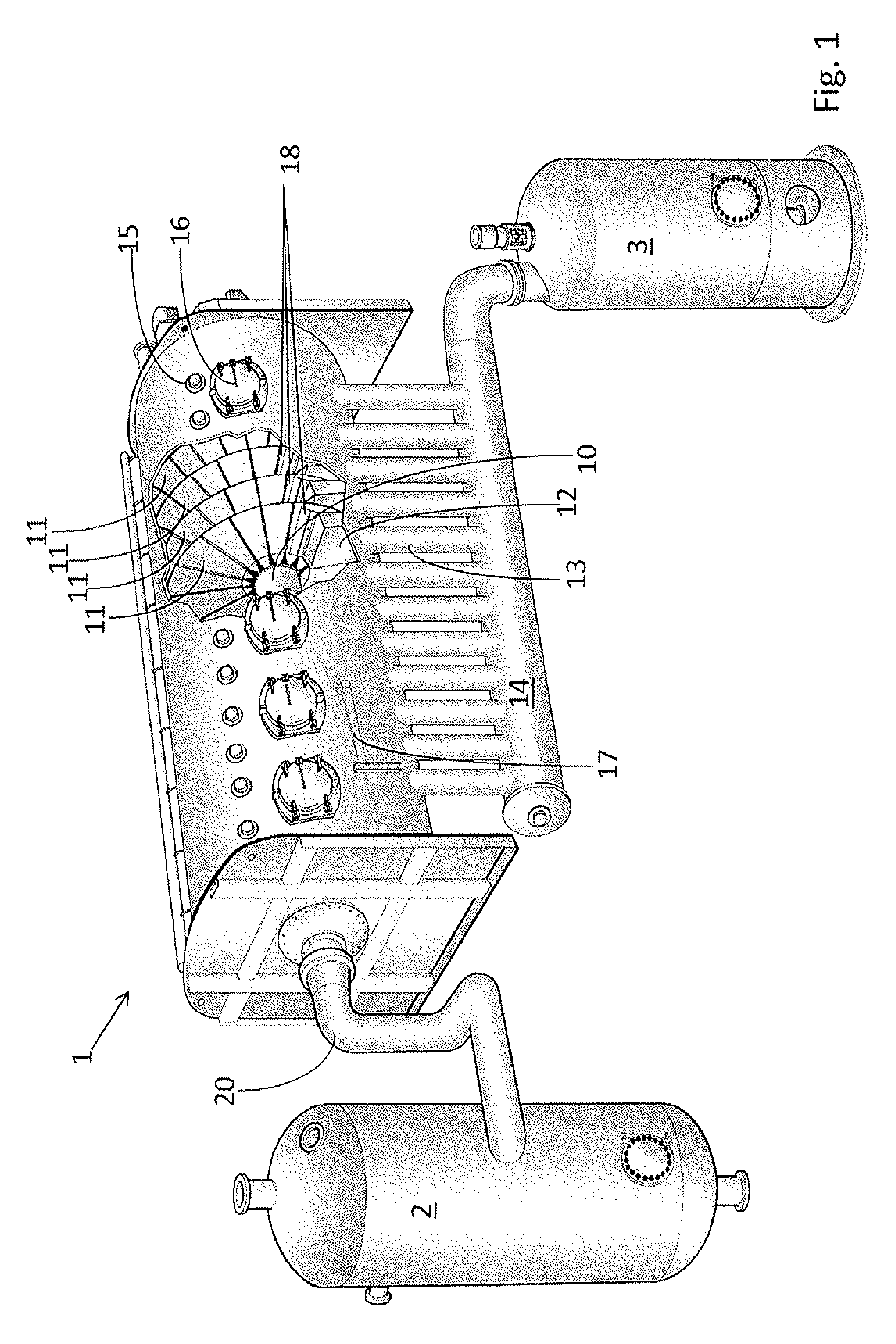
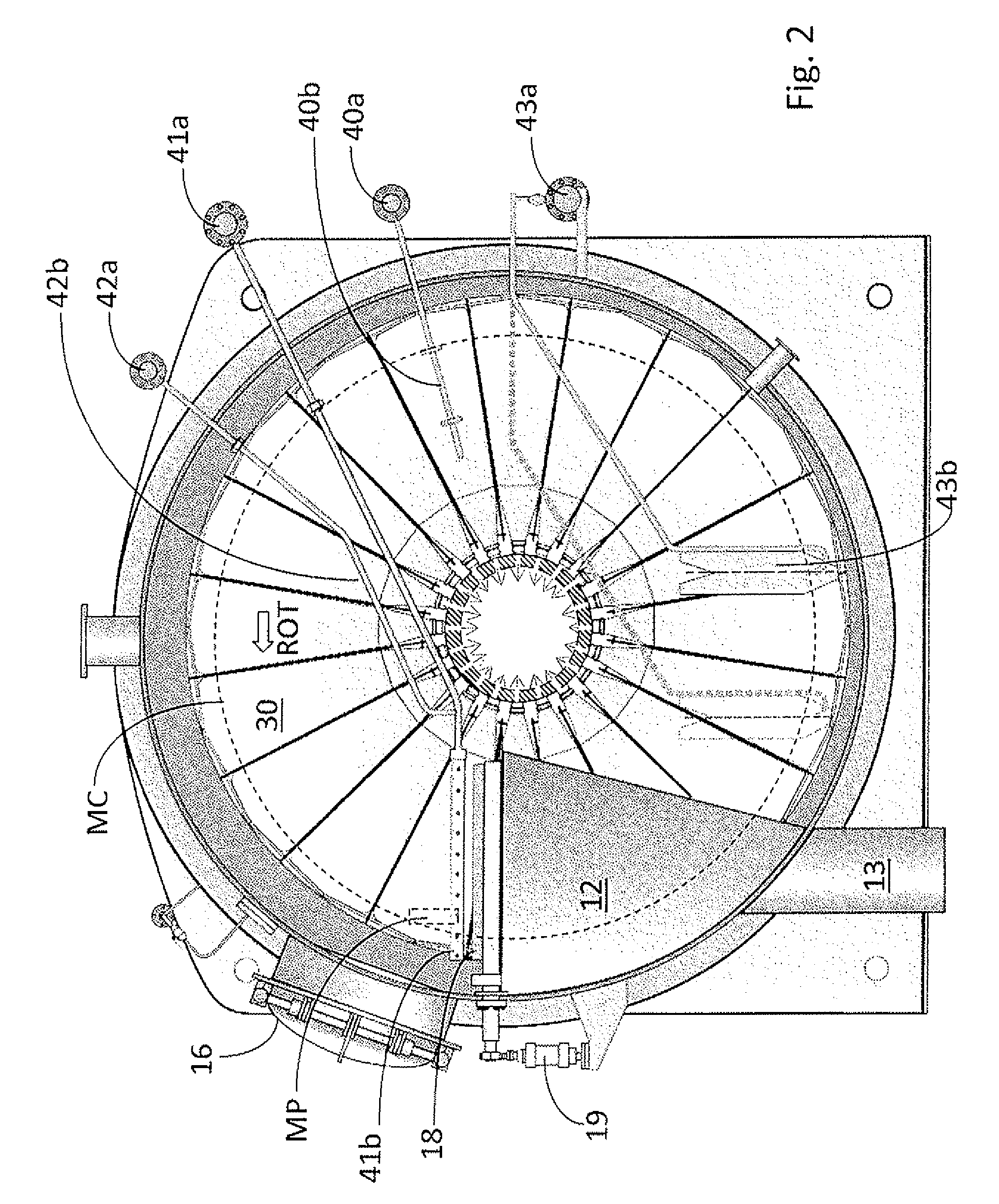
[0033]FIG. 1 shows a disc filter 1, here in the form of a disc filter under pressure in which the discs are inside a pressure vessel. The pressure vessel has been drawn partly opened in the drawing in order to show four filter discs, which are fixed arranged on and co-rotating with a shaft 10. A lime sludge chute 12 is located between the discs 11, on the upper edge of which chute is located a scraper 18 parallel to the surface of the discs. Lime sludge that is scraped from the filter falls into the lime sludge chute 12, down to the chute connection pipe 13 and onwards to a collection pipe 14, before the lime sludge finally reaches the lime sludge tank 3. Pure filtrate, white liquor in the case in which this is a white liquor filter, passes through the surfaces of the discs and is led down to the shaft 10, which is a conventional hollow shaft, and onwards through the filtrate line 20 to a filtrate tank 2. This drawing shows a filter with 11 filter discs. The drawing shows also a reg...


PUM

PropertyMeasurementUnit
radiusaaaaaaaaaa
radius R1aaaaaaaaaa
distanceaaaaaaaaaa

Abstract

The method and equipment relates to the measurement of deflections of filter sectors in a disc filter. The filter discs in the disc filter are constituted by a number of filter sectors, and the distance between a position fixed relative to the filter, most commonly the scraper itself, and the filter surface is conventionally measured by manual measurement methods. The equipment is instead used that has a measuring head with a quick-release coupling for its mounting fixed in the filter, and a position sensor in the measuring head that measures the distance between the measurement arrangement and the surface of the filter disc in order to form momentary measurement results. The momentary measurement results are transferred by a data transfer link from the measurement arrangement to a data collection unit PC that has a memory.

Description

PRIOR APPLICATION[0001]This application is a U.S. national phase application based on International Application No. PCT / SE2013 / 050684, filed 12 Jun. 2013 that claims priority from Swedish patent application number 1250623-4 filed 13 Jun. 2012.TECHNICAL AREA[0002]The present invention concerns a method and equipment for the measurement of filter sectors in disc filters.THE PRIOR ART[0003]Disc filters are used at several process positions in a paper pulp mill, not only as fibre filters but also as filters in the causticisation process.[0004]Fibre suspensions are dewatered in fibre filters and the collected fibre cake that forms on the filter discs during one rotation is scraped off in its entirety.[0005]Disc filters are used in the causticisation during chemical recycling, however, in a completely different manner, where a technology known as “precoating” of the filter surface is most often used. Independently of whether the filters are green liquor, white liquor or lime sludge filter...

Claims


Application Information

Patent Timeline
Patent Type & Authority Patents(United States)
IPC IPC(8): G01B5/20G01B3/22G01B5/30D21C9/06B01D33/21
CPCB01D33/21G01B3/22G01B5/20G01B5/30D21C9/06B01D33/804B01D37/02D21C11/0064G01B3/12G01B11/00
Inventor ROWE
Owner VALMET AB
Learn More