
Fractional beam forming network antenna

a network antenna and beam technology, applied in the field of antennas, can solve the problems of lack of flexibility in beam width and multi-input/multi-output capabilities, and achieve the effect of narrowing the beam width and increasing the quantity of antenna elements associated

Active Publication Date: 2016-06-14
HOWARD JOHN
View PDF5 Cites 1 Cited by
  • Summary
  • Abstract
  • Description
  • Claims
  • Application Information

AI Technical Summary

Benefits of technology

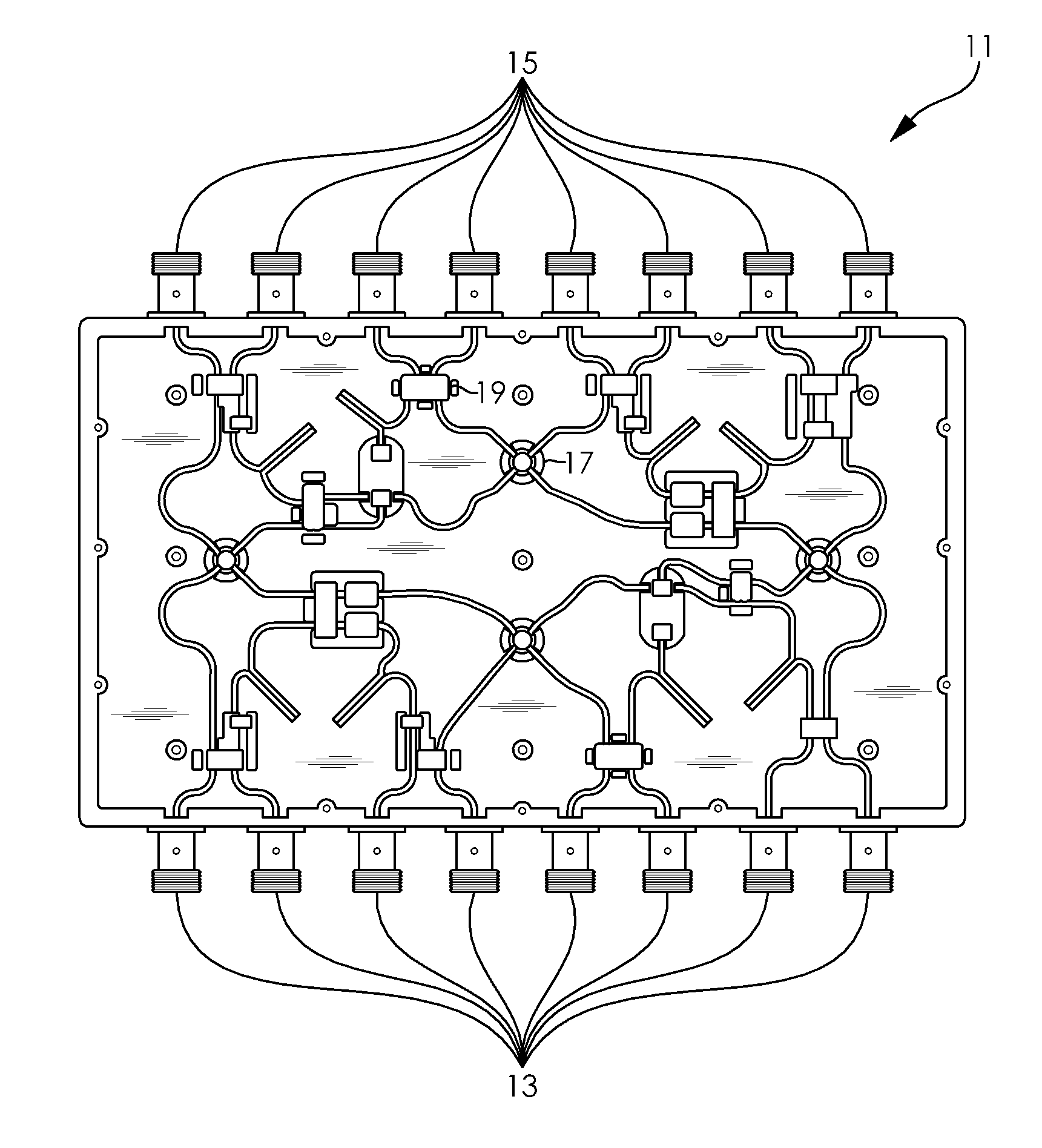
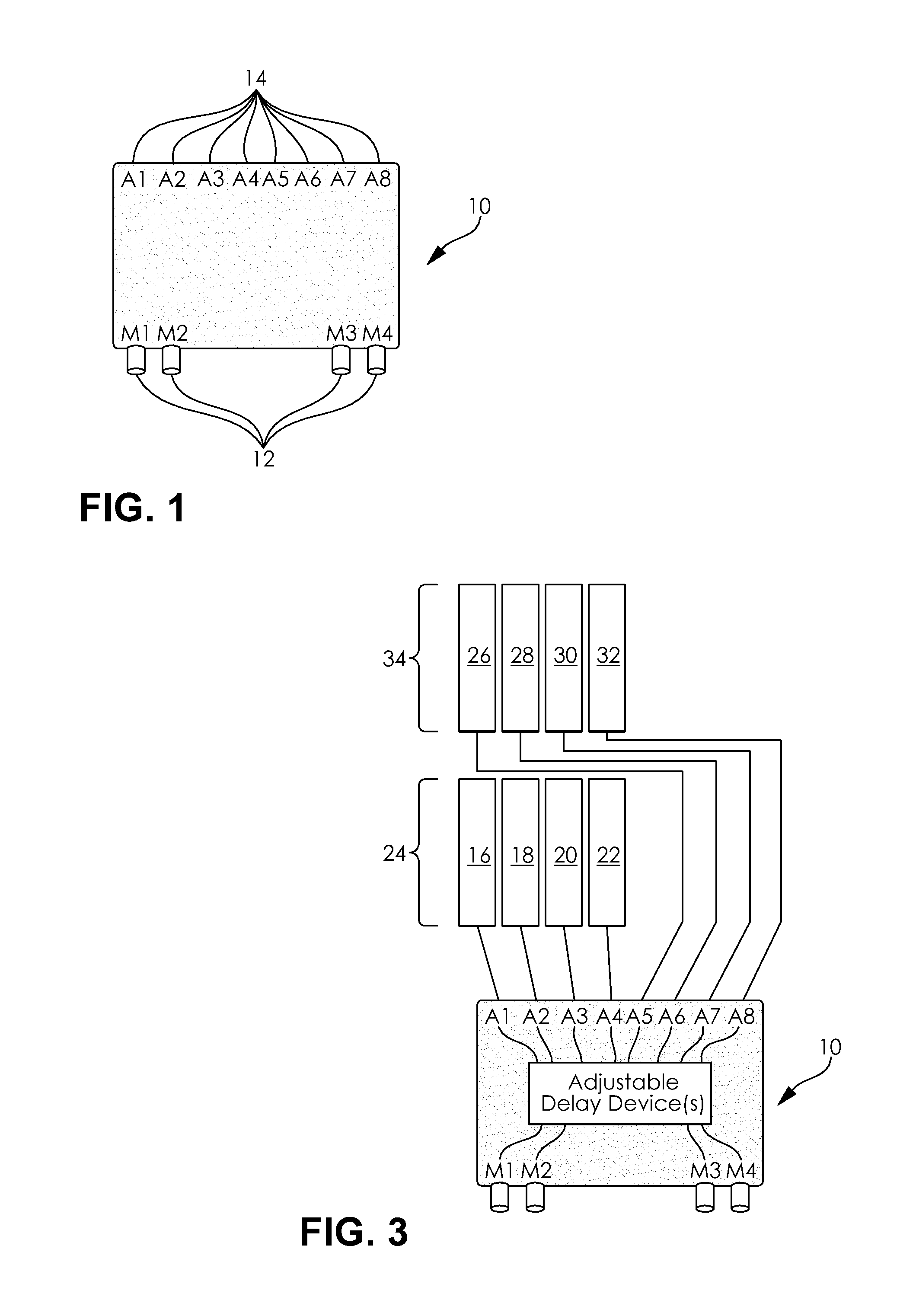
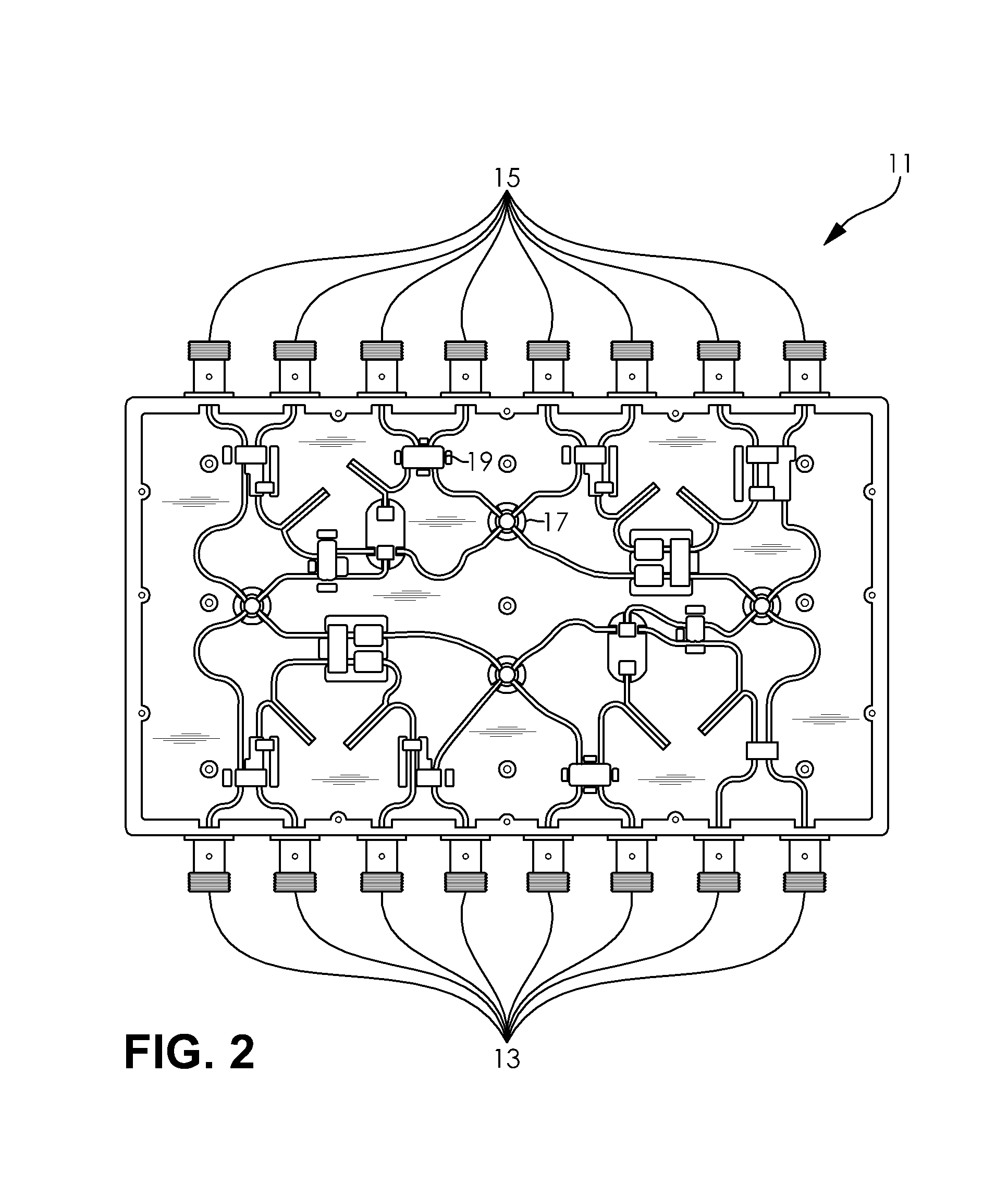
[0007]The beam forming network may include but is not limited to a 4×4 beam forming network, a 4×8 beam forming network, and / or an 8×8 beam forming network. Any combination of antennas to beams may be used in the embodiments disclosed herein. The delay device may be active and / or passive. The plurality of antennas may include an antenna column, which includes a plurality of antenna elements vertically disposed relative to each other. The plurality of antennas may include a plurality of antenna columns, and each of the plurality of antenna columns may include a plurality of antenna elements vertically disposed relative to each other. A beam width associated with the antenna column may be narrowed as a quantity of antenna elements associated with the antenna column is increased, and beam patterns associated with the plurality of antennas may overlap. The different elevation tilt associated with at least two of the plurality of antennas may be used to direct a beam pattern associated with at least two of the plurality of antennas to cover different distances from at least two of the plurality of antennas. The at least one delay device may include an adjustable delay, thereby enabling modification of a direction of a beam pattern associated with the plurality of antennas.
[0009]The method may include disposing the plurality of antennas vertically relative to each other in an antenna column. The method may include narrowing a beam width associated with the antenna column, and increasing a quantity of antenna elements associated with the antenna column. The method may include overlapping beam patterns associated with the plurality of antennas, and rotating the elevation tilt associated with at least two of the plurality of antennas to direct a beam pattern associated with at least two of the plurality of antennas to cover different distances from at least two of the plurality of antennas. The method may include adjusting the at least one delay device to modify direction of a beam pattern associated with the plurality of antennas.

Problems solved by technology

Some of the major challenges in designing antenna beam forming networks and systems include reducing and / or eliminating dead zones and a lack of flexibility in terms of beam width and multiple input / multiple output (MIMO) capabilities.

Method used


Image

  • Fractional beam forming network antenna
  • Fractional beam forming network antenna
  • Fractional beam forming network antenna

Examples


Embodiment Construction

[0018]Embodiments disclosed herein are configured to increase capabilities of beam forming networks and systems, which include doubling the total number of beams, providing multiple input-multiple output (MIMO) capability, and eliminating dead zones. Conventional beam forming systems typically exhibit dead zones, as well as reduced flexibility in terms of the beam width of the antenna and MIMO capabilities. One method of achieving these goals involves the use of a plurality of different large antennas, such as eight (8) antennas, each of which provides a narrow beam. However, this technique is both more costly and occupies a greater amount of space.

[0019]Embodiments disclosed herein accomplish these capabilities by utilizing an antenna system with two antennas and one beam forming network that provides dual beams, in which each antenna has a slightly different vertical (elevation) tilt and / or horizontal (azimuth) tilt (what is an acceptable range of variation for which the tilts can...


PUM


Abstract

A fractional beam forming network antenna includes a beam forming network and a plurality of antennas. The network includes input ports, output ports, and at least one delay device. The beam forming network couples input ports to the output ports through the at least one delay device. The antennas are vertically disposed relative to each other, and coupled to the output ports. At least two of the antennas include a different elevation tilt and / or azimuth rotation relative to each other. A method of fractional beam forming is provided, which includes coupling, using a beam forming network, input ports to output ports through at least one delay device; disposing a plurality of antennas vertically relative to each other; coupling the antennas to the output ports; and rotating at least two of the antennas in different elevation and / or different azimuth relative to each other.

Description

CROSS-REFERENCE TO RELATED APPLICATION[0001]This application claims the benefit of U.S. Provisional Application No. 61 / 610,507 filed on Mar. 14, 2012, the disclosure of which is incorporated herein by reference in its entirety.BACKGROUND[0002]1. Field[0003]Embodiments of the invention generally relate to antennas and, more particularly, relate to devices and methods that increase capabilities of beam forming networks.[0004]2. Related Art[0005]Some of the major challenges in designing antenna beam forming networks and systems include reducing and / or eliminating dead zones and a lack of flexibility in terms of beam width and multiple input / multiple output (MIMO) capabilities.SUMMARY OF THE INVENTION[0006]In accordance with one embodiment, a fractional beam forming network antenna is provided, which includes a beam forming network and a plurality of antennas. The beam forming network includes a plurality of input ports, a plurality of output ports, and at least one delay device. The be...

Claims


Application Information

Patent Timeline
Patent Type & Authority Patents(United States)
IPC IPC(8): H01Q3/22H01Q3/40H01Q3/26H01Q25/00
CPCH01Q3/2682H01Q3/40H01Q25/00
Inventor HOWARD, JOHN
Owner HOWARD JOHN
Learn More