Omnidirectional antenna system with bunching effect

A beamforming and dipole antenna technology, applied in antennas, resonant antennas, electrical short antennas, etc., can solve the problem of low antenna gain, achieve high gain, large frequency flexibility, significant beamforming effect and gain improvement effect Effect

Inactive Publication Date: 2021-10-22
UNIV OF ELECTRONICS SCI & TECH OF CHINA
View PDF3 Cites 0 Cited by
  • Summary
  • Abstract
  • Description
  • Claims
  • Application Information

AI Technical Summary

Problems solved by technology

The antenna has good omnidirectionality, but the half-power beam width is as wide as 100°, and the antenna gain is also low

Method used


Image

  • Omnidirectional antenna system with bunching effect
  • Omnidirectional antenna system with bunching effect
  • Omnidirectional antenna system with bunching effect

Examples


Embodiment 1

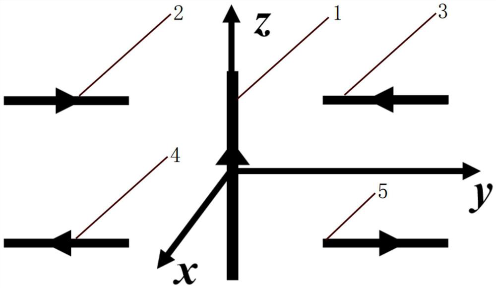
[0043] This embodiment provides a dipole antenna array with a beamforming effect, and its structural diagram is as follows figure 1 shown, including dipoles and parasitic dipoles;

[0044] In the Cartesian coordinate system, dipole 1 is placed along the z-axis, which is the #0 feed dipole, the current is along the positive direction of the z-axis, and the current amplitude is I 0 ; On the yoz plane, in the area of ​​z>0, y1 , I 0 / I 1 = 1.2, the center distance from the z axis is d=0.25λ, the distance from the y axis is h=0.05λ, λ is the wavelength corresponding to the working frequency of the dipole antenna array; mirror #1 parasitic dipole 2 along the xoz plane (The current direction is mirrored at the same time), and #2 parasitic dipole 3 is obtained; #1 parasitic dipole 2 and #2 parasitic dipole 3 are rotated n times around the z axis with an angle α, n is a natural number, and the first ( 2q+1) parasitic dipole and (2q+2)th parasitic dipole, 0≤q≤n, nα≤360°, in the prese...

Embodiment 2

[0047] This embodiment provides an ultra-low-profile omni-directional antenna system with a beamforming effect, and its top view is as follows image 3 As shown, the side view is as Figure 4 As shown, it includes two radiators, two dielectric substrates, three shorting nails 8 and four nylon support columns 9; the first radiator is located on the upper surface of the first dielectric substrate, and the second radiator is located on the second dielectric substrate The lower surface; the first dielectric substrate 41 and the second dielectric substrate 42 are circular dielectric substrates with the same size and material, and an air gap 42 is left between the first dielectric substrate and the second dielectric substrate; four nylon posts 9 are located between the two In the middle of the dielectric substrate, near the edge of the dielectric substrate, it plays a supporting role;

[0048] The two radiators have the same structure, including a circular active patch 6 and six I-...

Embodiment 3

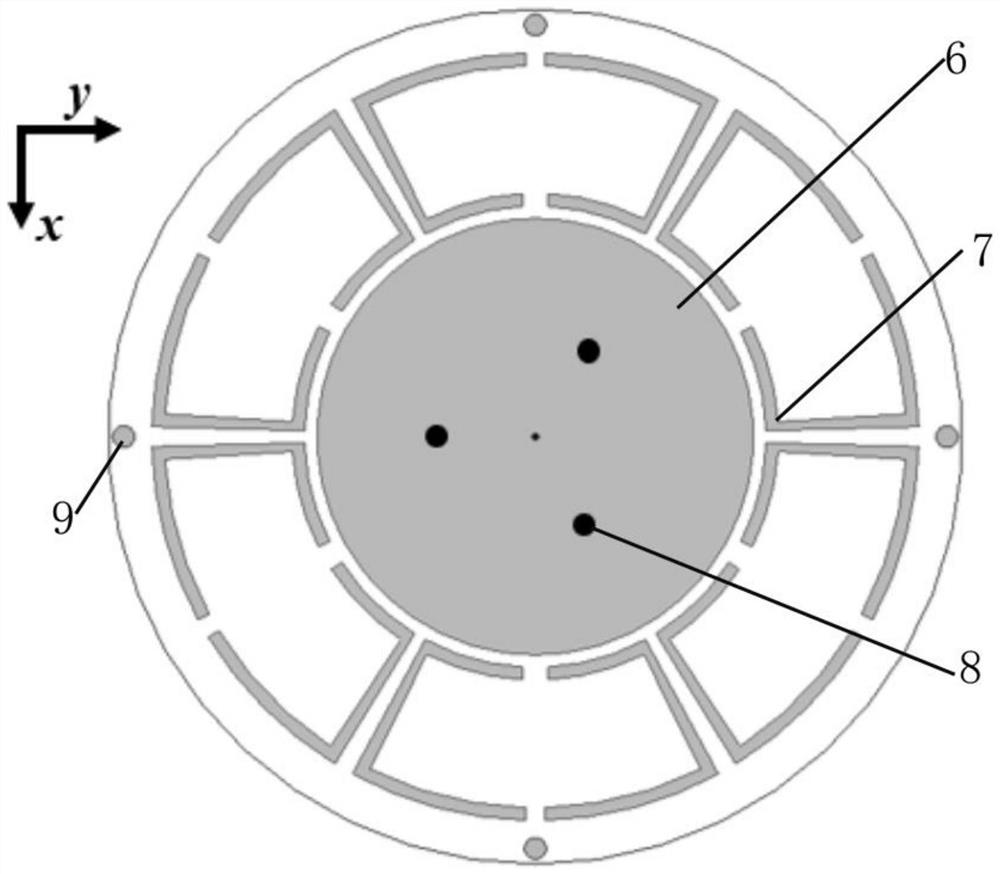
[0061] This embodiment provides an ultra-low-profile omni-directional antenna system with a beamforming effect, and its top view is as follows Figure 6 As shown, the cross-sectional view is shown in Figure 7 As shown, it includes a radiator, a dielectric substrate 72, a metal floor 64 and five shorting nails 63;

[0062] The radiator is located on the upper surface of the dielectric substrate; the radiator includes a circular active patch 61 and six T-shaped parasitic units 62; the center of the circular active patch coincides with the center of the dielectric substrate; the T-shaped parasitic unit along the circular The circumference of the active patch is evenly arranged, and the transverse arc-shaped branches of the T-shaped parasitic unit are parallel to the circumference;

[0063] The metal floor is located on the lower surface of the dielectric substrate, and the radius of the circular active patch < the radius of the metal floor < the radius of the circular dielectri...


PUM


Abstract

The invention discloses a dipole antenna array with a bunching effect as a theoretical model, provides two ultra-low profile omnidirectional antenna systems with bunching effects based on the theoretical model, and belongs to the technical field of antennas. Compared with a single dipole (namely an uncompressed beam), the dipole antenna array disclosed by the invention has the advantages that narrower beam width and higher gain are obtained, the bunching target is realized, and theoretical guidance is provided for the design of an actual antenna system. According to the two ultra-low profile omnidirectional antenna systems with the bunching effect, the remarkable bunching effect and gain improvement effect are achieved while the ultra-low profile is kept, and the two ultra-low profile omnidirectional antenna systems can be well applied to a limited space and a specific scene; and the design has great frequency flexibility, and an antenna system working at other frequencies (such as 2G, 4G and the like) can be easily designed, so that corresponding theories and engineering technologies in the antenna field are further enriched and developed.

Description

[0001] This application is a divisional application of a patent application with an application date of November 20, 2020, an application number of 202011312934.0, and an invention titled "Omnidirectional Antenna System with Focusing Effect". technical field [0002] The invention belongs to the technical field of antennas, and in particular relates to an omnidirectional antenna system with beam focusing effect. Background technique [0003] According to the radiation pattern of the antenna, the antenna is divided into two categories: directional antenna and omnidirectional antenna. In complex communication scenarios, some antennas are required to radiate omnidirectionally, that is, the antenna radiates uniformly at 360° in the horizontal plane and has a certain beam width in the vertical plane. At present, omnidirectional antennas have been widely used in point-to-multiple communications, mobile communications, satellite communications, and space vehicles. For an omnidirec...

Claims


Application Information

Patent Timeline
Patent Type & Authority Applications(China)
IPC IPC(8): H01Q9/28H01Q1/50H01Q1/38H01Q1/48
CPCH01Q9/285H01Q1/50H01Q1/38H01Q1/48
Inventor 熊江陈浩亮胡雅丽
Owner UNIV OF ELECTRONICS SCI & TECH OF CHINA
Why Eureka
Try Eureka