Air gun firing control device

a control device and air gun technology, applied in the direction of compressed gas guns, white arms/cold weapons, weapons, etc., can solve the problems and achieve the effect of reducing working resistance and convenient fitting

Active Publication Date: 2016-06-21
CHO CHAO HSIUNG
View PDF22 Cites 5 Cited by
  • Summary
  • Abstract
  • Description
  • Claims
  • Application Information

AI Technical Summary

Benefits of technology

[0005]The primary objective of the present invention lies in a device that uses a purely mechanical trigger unit to achieve controlling single firing and continuous firing modes. The device primarily comprises an auxiliary select continuous firing clasp simply and conveniently fitted in a single firing control system. After a limiting cam directs a shearing pressure surface of a trigger to rise, then the horizontal height position of a firing clasp increases, and the upper edge of the select continuous firing clasp causes the midriff of a jumping bar to shear across and correspondingly change the operating angular position of a jumping bar. The jumping bar is thus unable to fully intervene with a firing tube, and the firing tube is able to freely move back and forth, thereby achieving the objective of enabling purely mechanical firing control.
[0006]A further objective of the present invention lies in the structured trigger unit supported by a base and integrated into a single device, and which is able to be inserted into or assembled into the gun body, thereby facilitating assembly and disassembly for maintenance purposes.
[0007]The third objective of the invention lies in the select continuous firing clasp of the trigger unit being composed from the overlapping of at least two movable round pins. And the select continuous firing clasp is movable located in a settling groove defined in the base. Furthermore, the select continuous firing clasp uses point contacts and rolling motions between the outer circumferences of the two round pins and each structural member to significantly reduce working resistance.

Problems solved by technology

Furthermore, the select continuous firing clasp uses point contacts and rolling motions between the outer circumferences of the two round pins and each structural member to significantly reduce working resistance.

Method used


Image

  • Air gun firing control device
  • Air gun firing control device
  • Air gun firing control device

Examples


Embodiment Construction

[0017]Regarding the description of the operating mechanisms and operating states of the present invention, please refer to the description of the diagrams as follows:

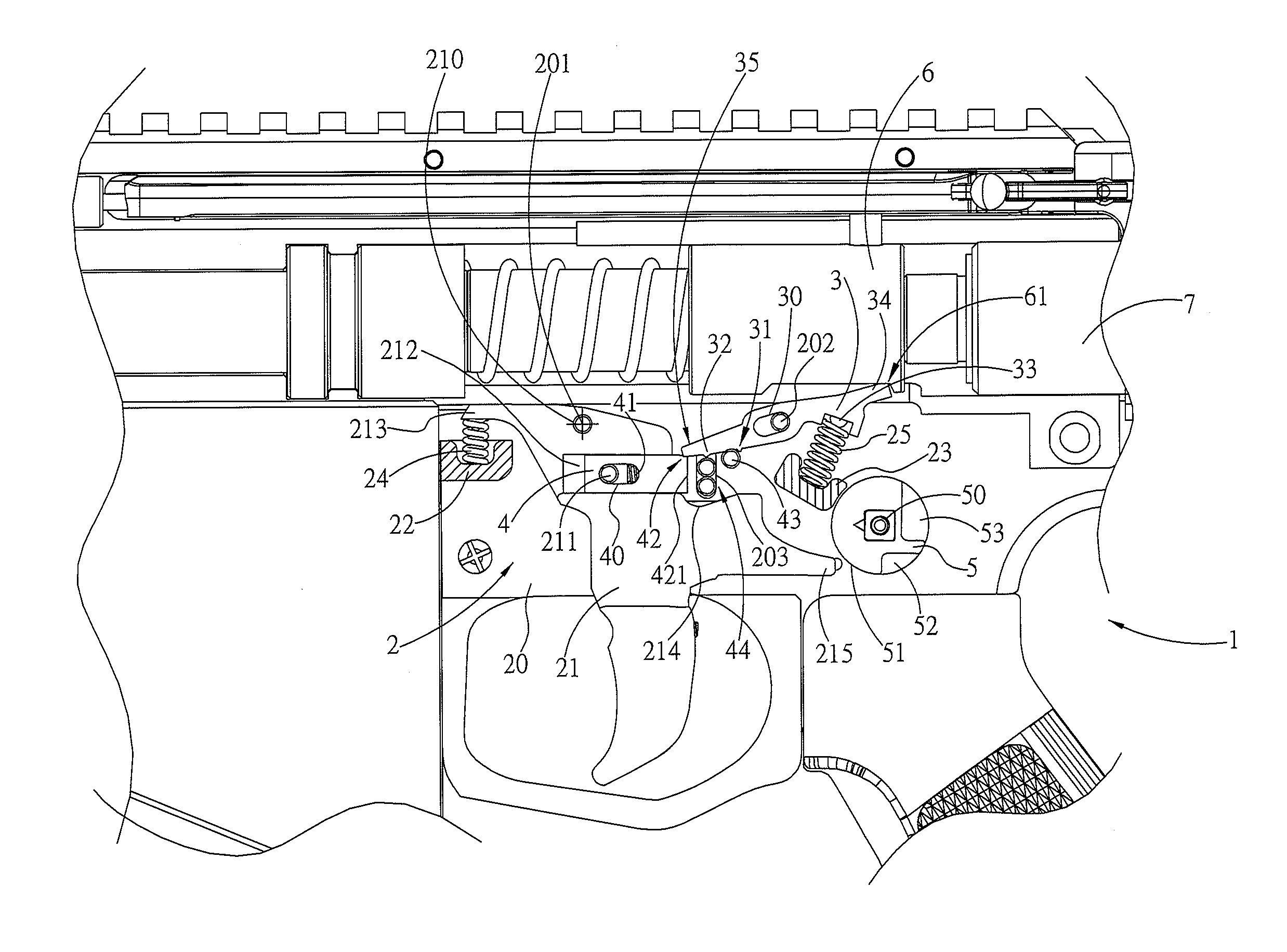
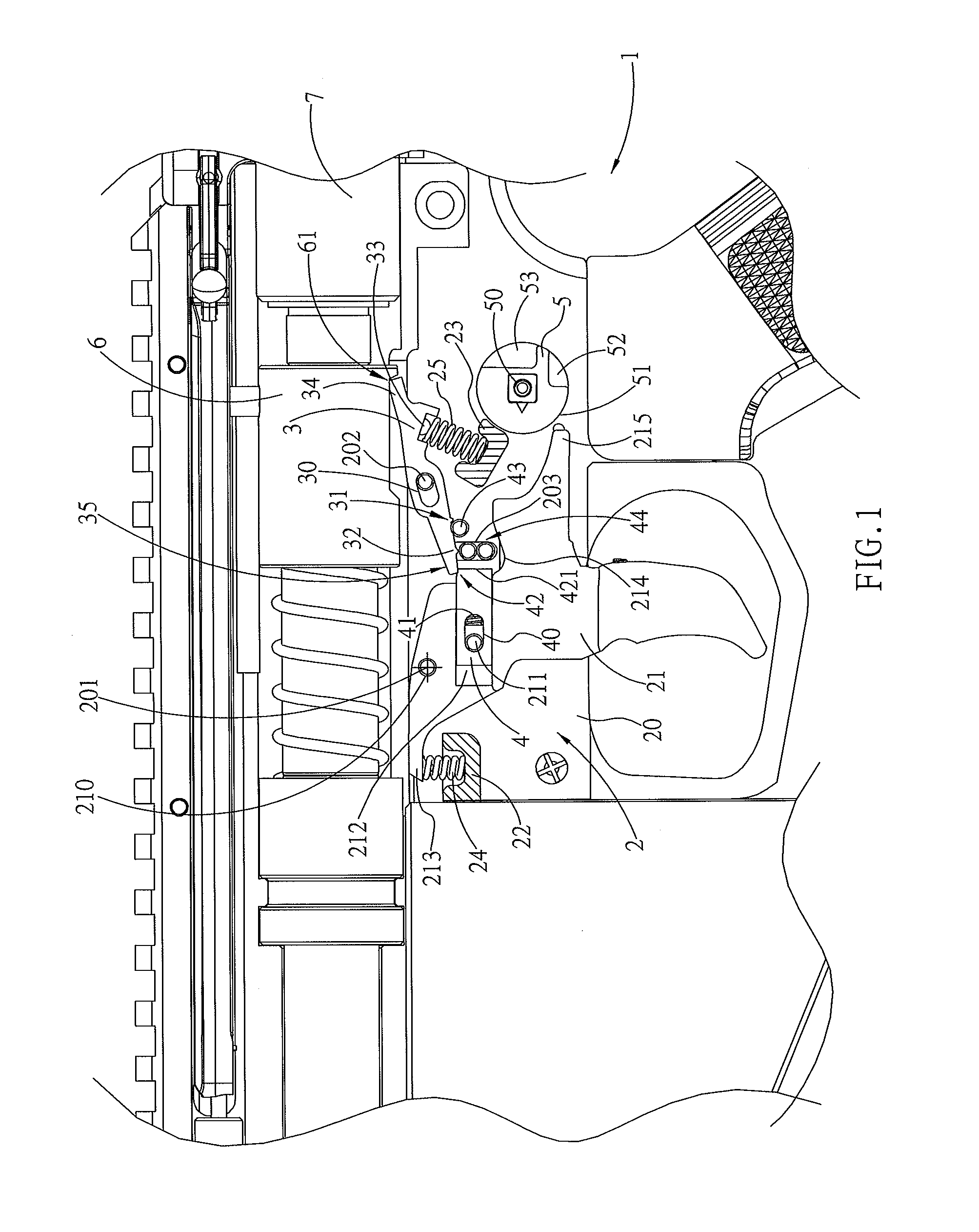
[0018]Referring first to FIG. 1, The present invention provides a device for controlling the firing of a game air gun, and a firing control operating system of the present device is depicted in FIG. 1, wherein the inner structure of a gun body 1 is provided with a trigger unit 2, which is an assembly that is directly pieced together or uses an insertion method (which includes any type of cartridge concept, and thus not further detailed herein).

[0019]The trigger unit 2 is basically provided with a base 20, the interior system of which is connected with a trigger 21, as well as a jumping bar 3 and a limiting cam 5. A shaft hole 210 is provided within an area on the upper end of the trigger 21, and the shaft hole 210 enables a central shaft 201 of the base 20 to be movable pin joined to the trigger 21. Accordingly, after a...


PUM


Abstract

Pressurized air from an air pressure bottle creates the firing motive force for game firearms. After accumulating sufficient pressure, the pressurized air is channeled to the gun chamber to achieve a firing objective. Using an application system for single firing, a purely mechanical firing control device is formed as an integral body to achieve single firing and continuous firing, and which is simply fitted with an auxiliary component to assist in achieving continuous firing. The auxiliary component is located in the swinging path of a cocking trigger. The select continuous firing clasp is pushed upward by the trigger and supports a jumping bar, which causes the jumping bar to lose its clasping retaining capacity on a firing tube to achieve a continuous firing operation.

Description

BACKGROUND OF THE INVENTION[0001]1. (a) Field of the Invention[0002]The present invention provides a purely mechanical firing control device, and more particularly uses an auxiliary control component to assist in achieving continuous firing control under a single firing operation mode as a basis.[0003]2. (b) Description of the Prior Art[0004]In general, firearms that use air pressure as the power source are used in air guns for game use, and the manufacturing cost is not high. However, after a long history of development, and under low cost conditions, the industry has also created realistic exteriors for the air guns and simulation of realistic operating modes, such as the ability to load bullets from a cartridge magazine, and shooting modes enabling single or continuous firing. The continuous firing mechanism of such designs generally uses a battery circuit operated electromechanical valve system to achieve a continuous firing frequency operation, and to operate under single firin...

Claims


Application Information

Patent Timeline
Patent Type & Authority Patents(United States)
IPC IPC(8): F41B11/00F41B11/70F41A19/10F41A19/03F41A19/00
CPCF41A19/10F41A19/03F41B11/70
Inventor CHO, CHAO-HSIUNG
Owner CHO CHAO HSIUNG
Why Eureka
Try Eureka