Roaming mobile sensor platform for collecting geo-referenced data and creating thematic maps

a sensor platform and mobile technology, applied in the field of mobile sensor platforms, can solve the problems of frequent bridge deck and pavement deterioration, scarce benefit of civil infrastructure from the latest advances in sensor technology, and low efficiency of civil infrastructur

Active Publication Date: 2016-06-28
NORTHEASTERN UNIV
View PDF15 Cites 13 Cited by
  • Summary
  • Abstract
  • Description
  • Claims
  • Application Information

AI Technical Summary

Benefits of technology

[0007]The invention provides a roaming sensor system for the monitoring of civil infrastructure such as roads and bridge decks. One or more vehicles of a type that regularly travel on roads and highways are used to collect and integrate sensor measurements and to perform onboard assessments about subsurface integrity of roadways and bridge decks. The system permits the collection of spatial and temporal data whose coverage over time far exceeds that of vehicles that are sent out for the sole purpose of collecting data in a particular area. The system can be combined with the use of dedicated vehicles in specific areas to complement the data collected by the system. The roaming sensor system of the present invention provides accurate, up-to-date roadway and bridge deck condition information without setting up work zones or stopping traffic. It therefore eliminates the need for dangerous and expensive work zones. The roaming sensor system will also improve safety for the driving public and for inspection personnel. Collected and analyzed data can be made available to roadway and bridge deck decision makers in the public and private sector through a control center that manages data analysis and preparation of maps, charts, and other useful end products.

Problems solved by technology

Despite being the lifeline of commerce, civil infrastructure has scarcely benefited from the latest advances in sensor technologies.
Roadway work zones used for assessment and repair are a major source of traffic congestion, which results in lost productivity and wasted fuel.
Bridge deck and pavement deterioration frequently takes place below the surface and cannot be evaluated by visual means.
Concrete deck deterioration includes delamination arising from chloride-induced rebar corrosion, cracking caused by alkali silica reaction (ASR), and cracking caused by overloading or excessive vibration.
Pavement deteriorates due to internal moisture damage, debonding, and loss of subsurface support.
The presence of the overlay makes it more difficult to detect the subsurface deterioration, and the overlay can also develop damage due to debonding.
Pavement layers are subjected to extensive abrasion and deterioration from service loading (e.g., traffic) and environmental attacks (e.g., freeze-thaw, rain, road salts), and thus are subject to deterioration.
Common types of roadway damage are transverse cracks, longitudinal cracks, tracking, corrugation, potholes, delamination, and seepage.
The loss of adhesion may be caused by seepage from cracks or potholes.
Local debonding may span only several square centimeters and can be difficult to detect because the pavement surface remains intact.
Large area delaminations may develop into large cracks at the pavement surface and eventually cause large potholes and loss of pavement.
Feedback effects can complicate and accelerate damage progression.
Cracks and potholes are often accompanied by seepage.
The adhesion between asphalt and concrete deck is extremely vulnerable to water penetration.
This is most harmful to asphalt pavement.
Traditional bridge deck inspection methods, such as chain drag, half-cell potentials, and chloride contents are slow, require closures, and are often not effective.
However, these technologies suffer from the need for traffic closures and insufficient spatial data coverage, which has reduced their acceptance and reliability.

Method used


Image

  • Roaming mobile sensor platform for collecting geo-referenced data and creating thematic maps
  • Roaming mobile sensor platform for collecting geo-referenced data and creating thematic maps
  • Roaming mobile sensor platform for collecting geo-referenced data and creating thematic maps

Examples


example 1

GPS Positioning System

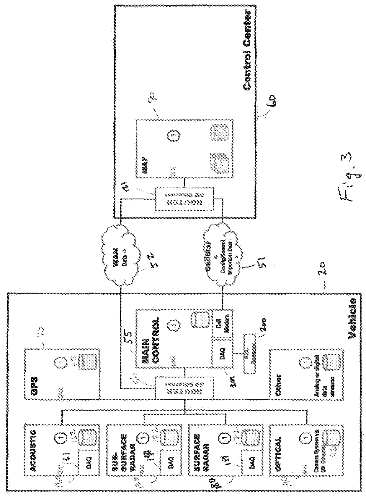
[0049]A delivery van was outfitted with a positioning system consisting of two GPS positioning systems, one with centimeter resolution and the other with meter resolution, an inertial navigation systems (INS) with 6 degrees of freedom, and a distance measurement instrument (DMI) in the form of a wheel-mounted survey / trigger wheel. Positioning system data streams from those four instruments were recorded by either a dedicated computer or a main controller, both installed in the van. An additional component of the positioning system was an accurate time stamping signal provided by a GPS-based timing board, which was used to correlate each of the data streams with the others for processing. All of the positioning data streams were processed by a custom algorithm to output the most accurate position based on the available data.

[0050]FIG. 4 shows an output obtained from the system. The van was driven around the National Center for Asphalt Technology (NCAT) test trac...

example 2

Acoustic Surface and Subsurface Sensing System

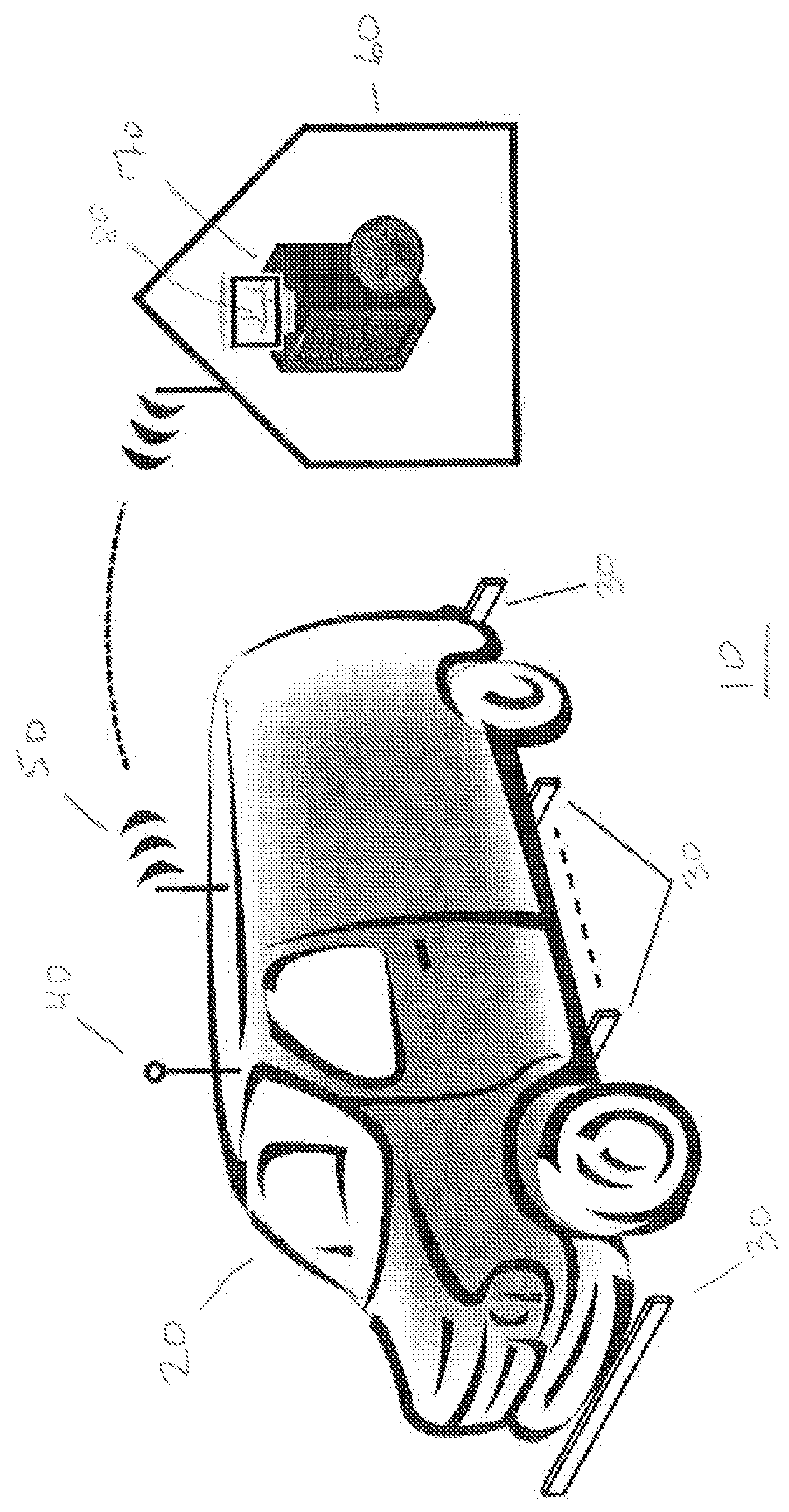
[0051]A surface wave-based sensor was developed to monitor and interpret road and bridge deck acoustic responses at ordinary driving speeds. The system was termed the Tire Excited Acoustic Sensor system (TEAS). A schematic of the system is shown in FIG. 5A. The sensor system uses acoustic noise signals generated by tires 22 of the roaming sensor system vehicle 20 during normal driving to distinguish defects in asphalt overlay and concrete roadbed, focusing on the early detection of poor bonding between asphalt and concrete deck, and extensive cracking. The objective was to measure acoustic waves generated by the system vehicle's own tires during normal driving and to extract the condition of the asphalt pavement on the road and the condition of the concrete deck beneath it.

[0052]In this sensor system the tire is used as a mechanical source. Each tire transmits approximately one quarter of the vehicle weight to the road surface, which mec...

example 3

Air-Coupled Ground Penetrating Radar (GPR) Array

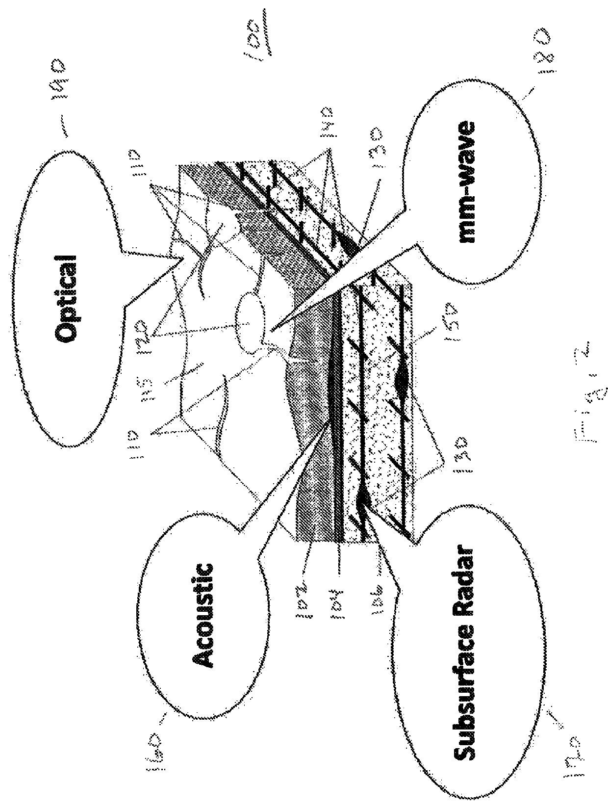
[0058]A GPR array was designed to rapidly and automatically sense subsurface anomalies in roadways and bridge decks indicative of deterioration. Such anomalies would otherwise be invisible from a surface inspection of the road surface (FIG. 2). The fundamentals of GPR array technology to map the subsurface for many applications including utility mapping and roadway and bridge deck layer mapping and imaging is documented elsewhere (see, e.g., Slob, E., Sato, M., and Olhoeft, G., 2010, Surface and borehole ground-penetrating-radar developments: Geophysics, Vol. 75, p. 75A103-75A120; and Birken, R., Miller, D., Burns, M., Albats, P., Casadonte, R., Deming, R., DeRubeis, T., Hansen, T. and Oristaglio, M., 2002. Efficient large-scale underground utility mapping in New York City using a multi-channel ground-penetrating imaging radar system, Proc. SPIE, Vol. 4758, pp. 186-191). However, commercially available GPR array systems are not able to...


PUM


Abstract

A roaming sensor system collects data on the condition of roads and bridge decks and identifies and maps defects, including cracks, potholes, debonding, tracking, delamination, surface ice, surface water, and rebar corrosion. Data are collected by a vehicle or a fleet of vehicles driven at normal traffic speeds. The vehicle is outfitted with sensors that collect data using acoustic surface waves, ground penetrating radar, mm wave surface radar, and / or video images. The data are transmitted to a control center for analysis and distribution.

Description

CROSS REFERENCE TO RELATED APPLICATIONS[0001]This application claims the priority of U.S. Provisional Application No. 61 / 315,571 filed Mar. 19, 2010, entitled, ROAMING MOBILE SENSOR PLATFORM COLLECTING GEO-REFERENCED SENSOR DATA AND CREATING THEMATIC MAPS, and of U.S. Provisional Application No. 61 / 434,559 filed Jan. 20, 2011, entitled TIRE EXCITED ACOUSTIC SENSING SYSTEM, Each of the aforementioned related applications is hereby incorporated by reference in its entirety.STATEMENT REGARDING FEDERALLY SPONSORED RESEARCH[0002]The research leading to this invention was carried out with U.S. Government support provided under a grant from the National Institute of Standards and Technology (NIST) Technology Innovation Program (TIP), Grant No. 70NANB9H9012. The U.S. Government has certain rights in the invention.BACKGROUND[0003]Civil infrastructure construction and maintenance represent a large societal investment. Despite being the lifeline of commerce, civil infrastructure has scarcely b...

Claims


Application Information

Patent Timeline
Patent Type & Authority Patents(United States)
IPC IPC(8): G01S13/00G01B11/25G01S15/89G01V3/12G01S13/88G01S13/89
CPCG01S13/885G01B11/2513G01S13/00G01S15/89G01V3/12G01S13/89G01S19/14
Inventor BIRKEN, RALFWANG, MING-LIANGRAPPAPORT, CAREY M.WADIA-FASCETTI, SARAMCDANIEL, J. GREGORY
Owner NORTHEASTERN UNIV
Why Eureka
Try Eureka