Method of using camera sensor interface to transfer multiple channels of scan data using an image format

a technology of image format and camera sensor, applied in the field of using camera sensor interface to transfer scan data using image format, can solve the problems of reducing the time available for decoding, wasting time and processing power, and both hardware and software utilized in this process present limitations, so as to increase the scan rate and reduce overhead

Active Publication Date: 2016-06-28
HONEYWELL INT INC
View PDF10 Cites 132 Cited by
  • Summary
  • Abstract
  • Description
  • Claims
  • Application Information

AI Technical Summary

Benefits of technology

[0012]An object of the present invention is to increase scan rates in an EIR terminal by moving data to the processor with less overhead so the processor can dedicate most of its time to performing the decoding algorithms instead of using this time transferring barcode data from the external circuitry.
[0013]Another object of the present invention is to utilize the camera sensor interface (CSI) for laser signal collection. The utilization of this interface by a laser signal, instead of only a CMOS (complementary metal-oxide-semiconductor) camera, integrates the heightened performance of image scanning with a laser scanner, into a hand held device, such as an EIR terminal.
[0014]The present invention enables the CSI to collect laser signals. The present invention enables laser scan data to be placed directly into the processor's memory space with reduced overhead. This is accomplished by pushing data to the processor at fixed time intervals using the CSI. Additionally, the data is packaged into well defined image frames along with the header information, allowing the processor to identify quickly if the data should be processed and if so, which elements should be processed together.
[0016]In an embodiment of the present invention, the data collected by the scanner, including but not limited to laser data, are pushed from the external hardware to the processor for decoding. The pushes occur at fixed time intervals. Pushing the data at fixed intervals eliminates the need for the processor to poll the external hardware for data. Thus, the processor time used to determine the availability of data can be allocated to other tasks within the EIR terminal.

Problems solved by technology

Mobile terminals (e.g., encoded information reading (EIR) terminals configured to read bar codes and / or other types of encoded information) waste time and processing power transferring bar code scan data from their electronic circuitry to their processors.
When multiple scan channels are decoded, both the hardware and the software utilized in this process present limitations.
The processor requires time to poll the external device constantly, which reduces the time available for decoding.
The processor searched through each piece of data to identify these regions which adds further overhead to the decoding process.

Method used


Image

  • Method of using camera sensor interface to transfer multiple channels of scan data using an image format
  • Method of using camera sensor interface to transfer multiple channels of scan data using an image format
  • Method of using camera sensor interface to transfer multiple channels of scan data using an image format

Examples


Embodiment Construction

[0024]The present invention provides a system and method for increasing the decoding speed when decoding images of decodable indicia, such as bar codes, with a terminal, such as an EIR terminal.

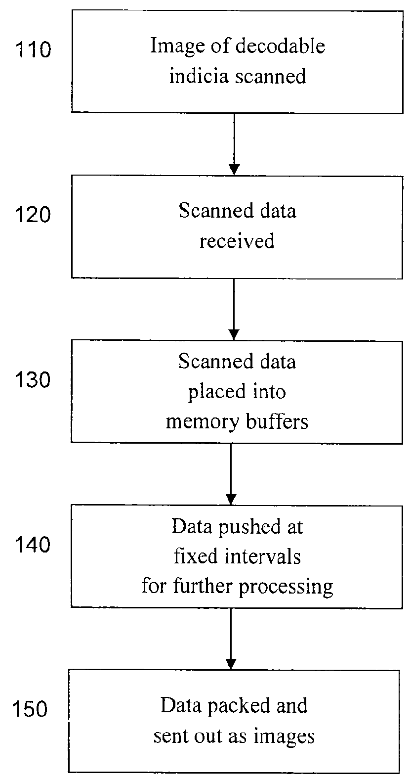
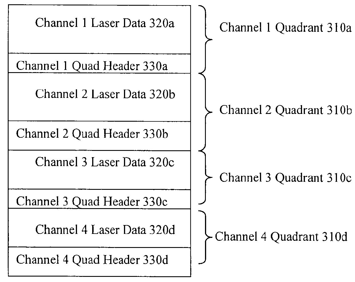
[0025]The present invention enables laser scan data to be placed directly into the processor's memory space with reduced overhead. At least one of three approaches is utilized to increase the decoding speed: 1) the CSI is utilized to place laser scan data into defined memory buffers; 2) laser data is pushed from the external hardware to the decoding processor at fixed time intervals; and 3) laser data is packaged into defined image frames and transmitted with header information.

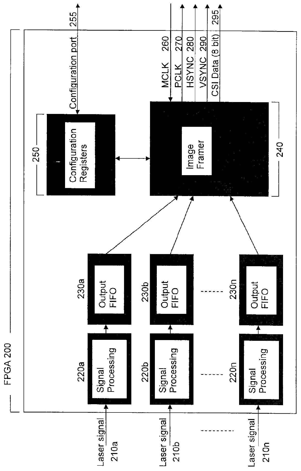
[0026]In an embodiment of the present invention, the external hardware used for the signal processing within the EIR terminal sends the data to the processor, emulating a camera senor interface, by performing the following functions: 1) reading data from each of the laser channels into memory; 2) packaging this data in...


PUM


Abstract

A computer system for decoding a signal of decodable indicia. The computer system includes a laser scanner configured that outputs a signal of decodable indicia and a microprocessor that include a camera sensor interface that is configured to receive the signal from the laser scanner.

Description

FIELD OF INVENTION[0001]The present invention provides a system and method for increasing the decoding speed when decoding images of decodable indicia, such as bar codes, with a terminal.BACKGROUND OF INVENTION[0002]Bar codes are graphical representations of data, images of decodable indicia, the most common of which are referred to as one dimensional (1D) and two dimensional (2D) bar codes. 1D bar codes are images that represent data by varying the widths and spacings of parallel lines. 2D bar codes are also images that represent data, but in addition to the parallel lines, or bars, a 2D bar code may contain rectangles, dots, hexagons and other geometric patterns in two dimensions. A common example of a 2D bar code is a Quick Response (QR) code. QR codes consist of black modules arranged in a square pattern on a white background. The data encoded in bar codes are interpreted by optical scanners and / or software.[0003]Bar codes were first scanned by special optical scanners called ba...

Claims


Application Information

Patent Timeline
Patent Type & Authority Patents(United States)
IPC IPC(8): G06K7/10G06K7/14
CPCG06K7/10821G06K7/10554G06K7/1404G06K7/1413G06K7/1417G06K19/06028G06K19/06037
Inventor WANG, YNJIUN PAULXIAN, TAOMIRAGLIA, MICHAEL VINCENTWILLIAMS, TIMOTHYELLIS, DUANENAHILL, JAMESLIU, YONGGIORDANO, PATRICK ANTHONYWILZ, DAVID
Owner HONEYWELL INT INC
Why Eureka
Try Eureka