

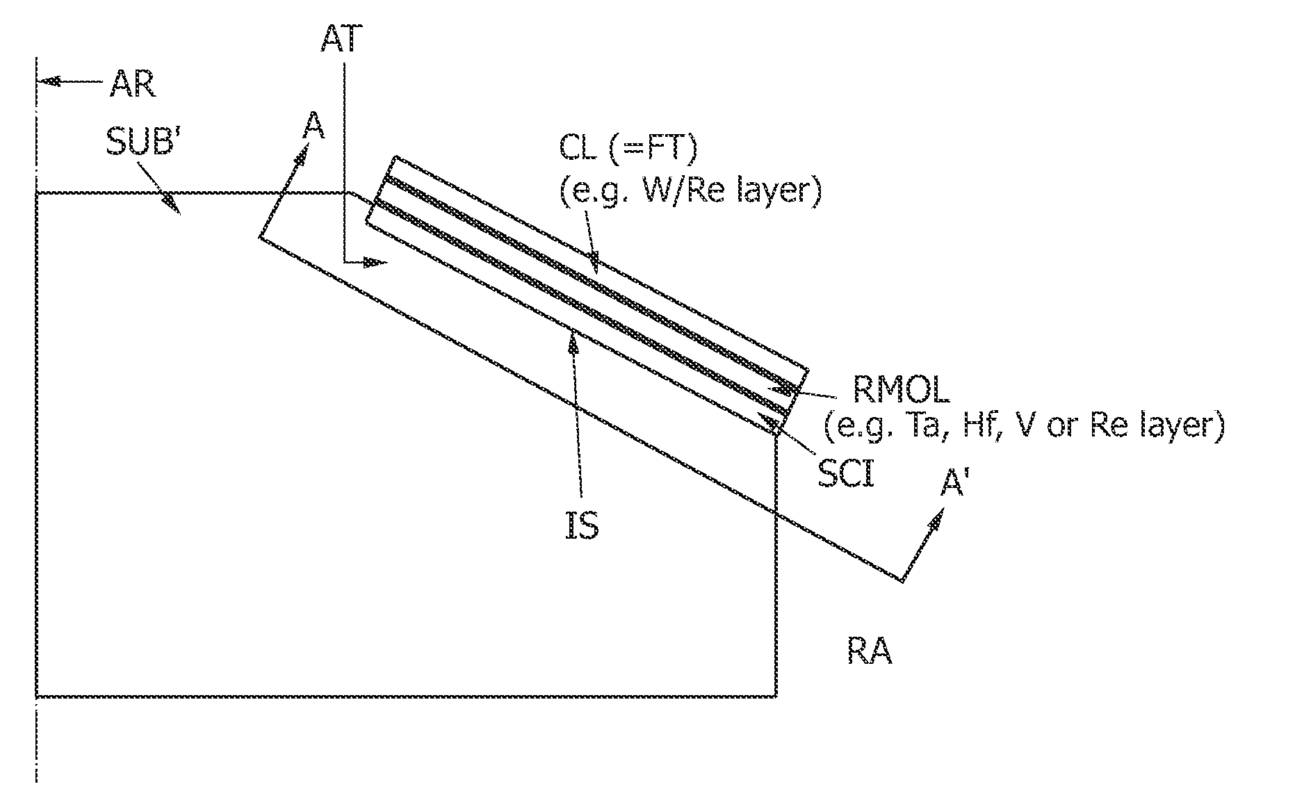
Attachment of a high-Z focal track layer to a carbon-carbon composite substrate serving as a rotary anode target
a carbon-carbon composite substrate and high-z focal track technology, applied in the direction of x-ray tube targets, x-ray tube targets and convertors, x-ray tube materials, etc., can solve the problems of prevalent coating cracks, achieve high-z focal track layer, improve the density of carbon matrix, and enhance the adhesion of silicon carbide/refractory
- Summary
- Abstract
- Description
- Claims
- Application Information
AI Technical Summary
Benefits of technology
Problems solved by technology
Method used
Image

Examples
Embodiment Construction
[0050]In the following, the hybrid anode disk structure according to an exemplary embodiment of the present invention, compared to the relevant prior art, will be explained in more detail and with reference to the accompanying drawings.
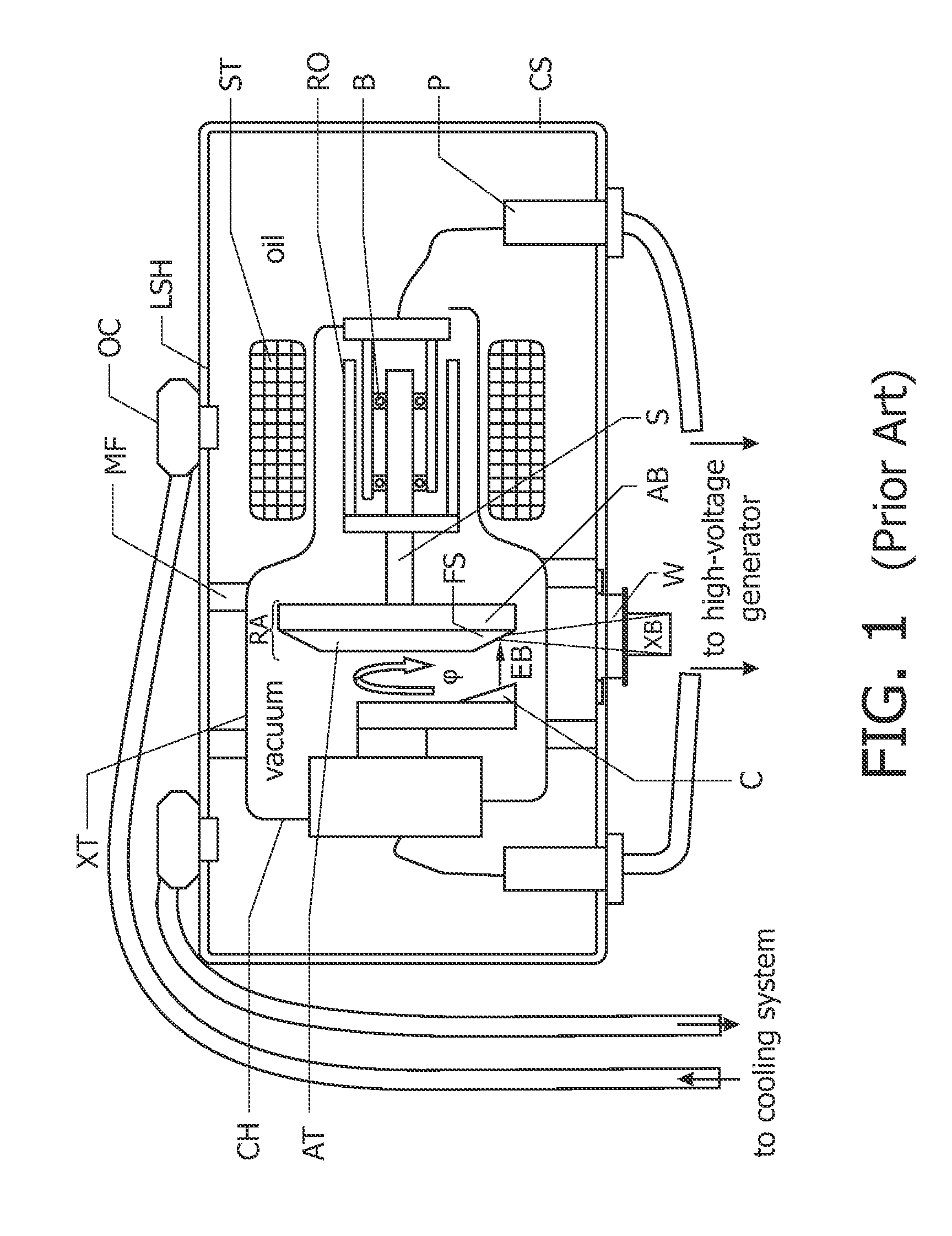
[0051]A schematic cross-sectional view of a conventional X-ray tube of the rotary anode type as known from the prior art is shown in FIG. 1. The X-ray tube comprises a stationary cathode C and a rotationally supported anode target AT fixedly attached to a rotary shaft S within an evacuated chamber CH given by a glass or metal-glass envelope. When being exposed to an electron beam EB of sufficient energy incident on a focal track region on an inclined surface of the anode target, said electrons being ejected from the anode target material due to a high voltage applied between the cathode and said anode, a conical X-ray beam XB is generated by the rotational anode target AT and emitted through a window W of a casing CS which contains the evacuated chamb...
PUM
| Property | Measurement | Unit |
|---|---|---|
| temperature | aaaaa | aaaaa |
| temperature | aaaaa | aaaaa |
| temperature | aaaaa | aaaaa |
Abstract
Description
Claims
Application Information