
System and methods for x-ray backscatter reverse engineering of structures

a reverse engineering and x-ray backscattering technology, applied in the direction of material analysis using wave/particle radiation, instruments, transportation and packaging, etc., can solve the problems of minor inconvenience, distortion, and unsuitability of van-mounted systems for interior use,

Active Publication Date: 2009-11-24
THE BOEING CO
View PDF47 Cites 42 Cited by
  • Summary
  • Abstract
  • Description
  • Claims
  • Application Information

AI Technical Summary

Benefits of technology

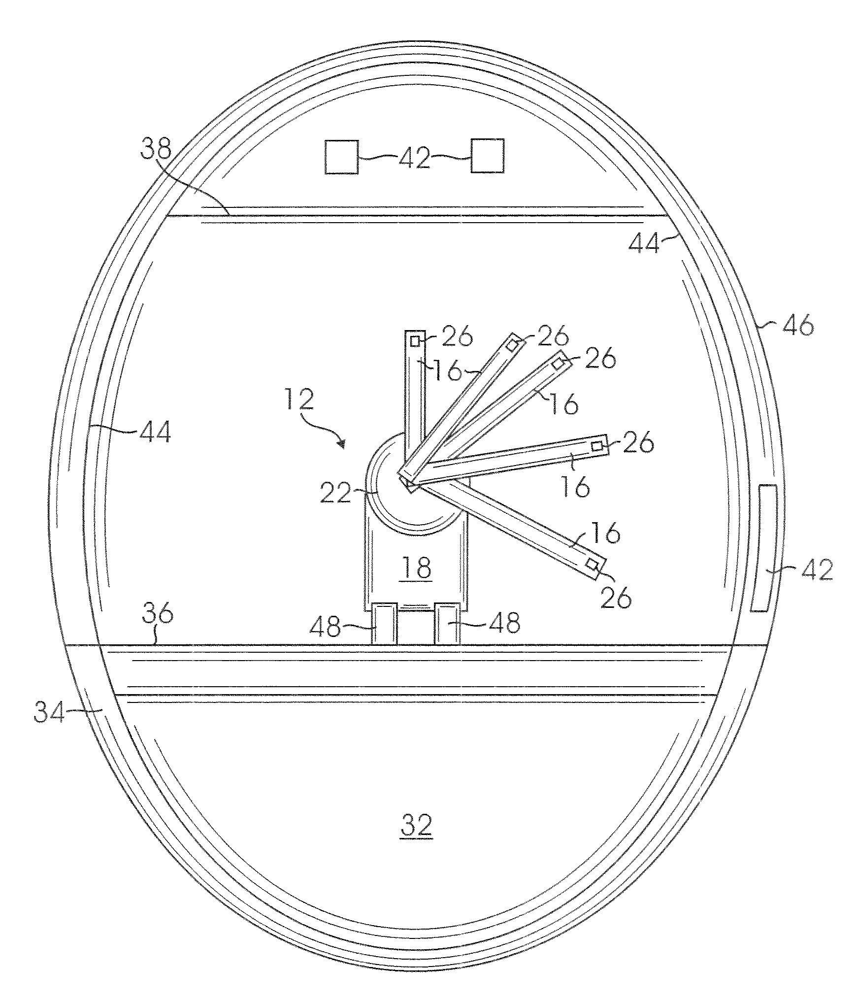
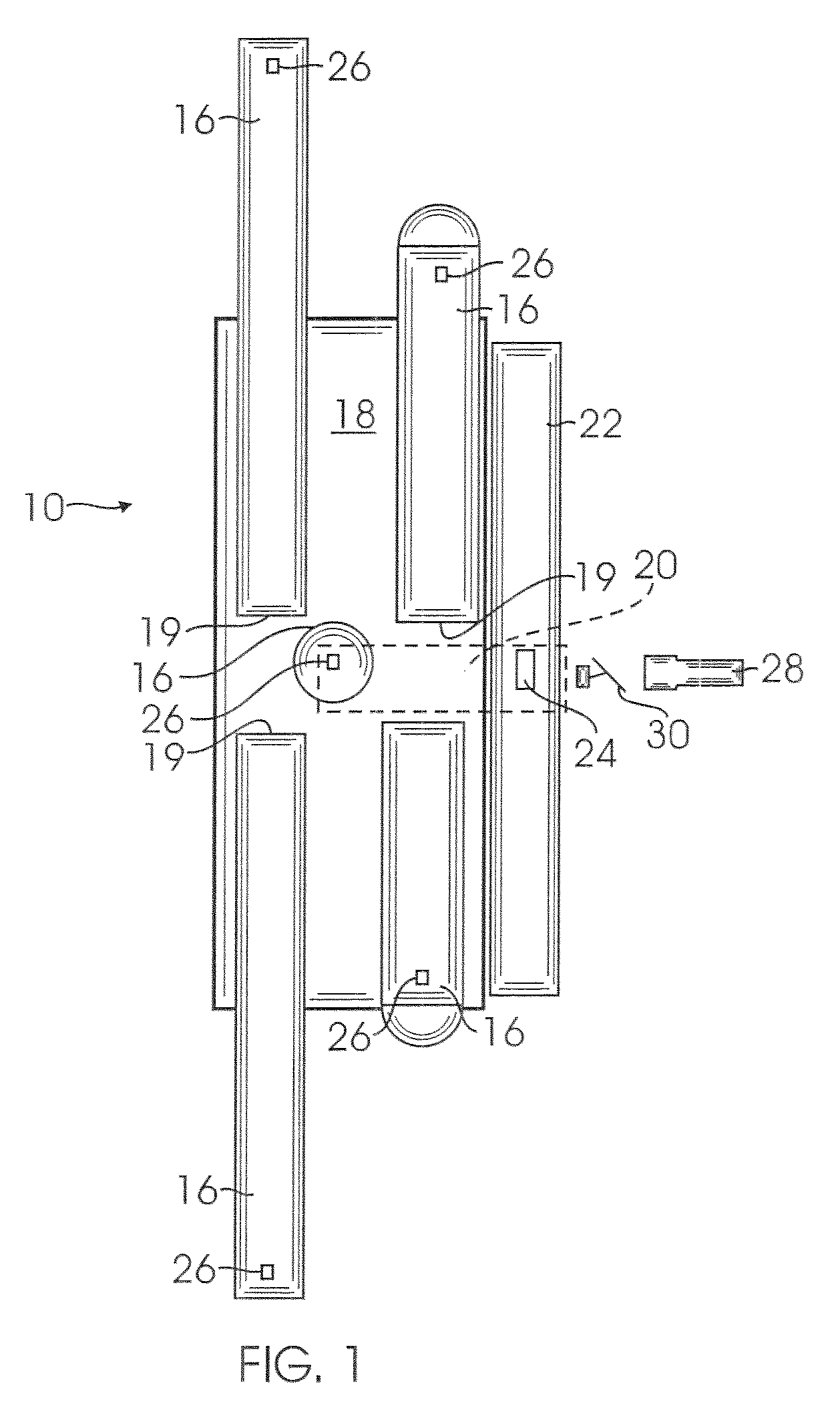
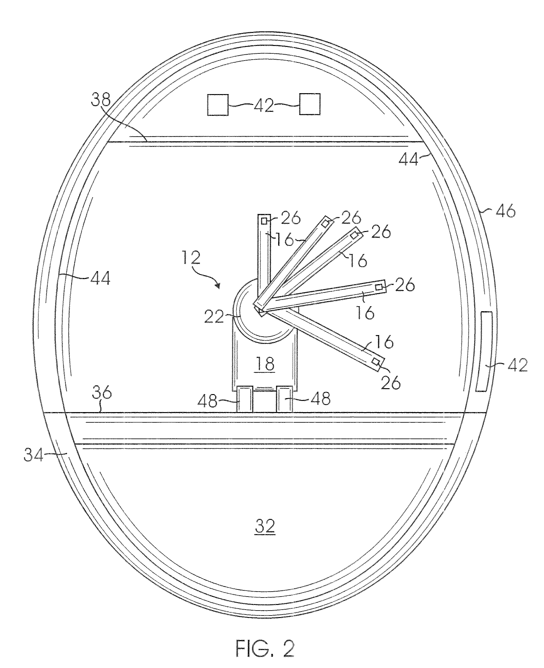
[0011]The preferred embodiments of the present system and methods for x-ray backscatter reverse engineering of structures have several features, no single one of which is solely responsible for their desirable attributes. Without limiting the scope of this system and these methods as expressed by the claims that follow, their more prominent features will now be discussed briefly. After considering this discussion, and particularly after reading the section entitled “Detailed Description of the Preferred Embodiments”, one will understand how the features of the preferred embodiments provide advantages, which include, without limitation, improved resolution, over prior art systems, high scanning speeds, field-of-view and effective scanning range versatile enough to work in various orientations and in environments of various size, the system is compact and lightweight so that it can be easily transported and used within confined spaces or in environments where weight is a consideration, and the system is both pointable and adaptable.
[0012]One aspect of the present system and methods for x-ray backscatter reverse engineering of structures includes the realization that there is a need for a high-speed, high-resolution, portable, articulated, transportable and lightweight x-ray back scattering system that limits image distortion and allows for inspection between structures, such as cabinets, overhead bins, and seats, and is capable of traveling through relatively narrow spaces.

Problems solved by technology

The large size of these van-mounted systems makes them unsuitable for use in interior spaces, such as inside an aircraft (except, perhaps, inside large cargo aircraft having ramp doors).
Such distortions present a minor inconvenience when searching for contraband, where the goal is merely to identify the presence of foreign objects to determine whether a closer investigation is warranted.
In a reverse engineering application, however, distortions present a major problem.
Conventional x-ray backscatter systems are also not able to account for objects within an aircraft, such as galleys, cabinets and seats.
Further, these systems do not have adequate scanning speed, robustness, ability to work in various orientations, scanning range, or field of view for aircraft reverse engineering applications.
They are also not tailored to detect and accurately depict the materials present on aircraft.

Method used


Image

  • System and methods for x-ray backscatter reverse engineering of structures
  • System and methods for x-ray backscatter reverse engineering of structures
  • System and methods for x-ray backscatter reverse engineering of structures

Examples


Embodiment Construction

”, one will understand how the features of the preferred embodiments provide advantages, which include, without limitation, improved resolution, over prior art systems, high scanning speeds, field-of-view and effective scanning range versatile enough to work in various orientations and in environments of various size, the system is compact and lightweight so that it can be easily transported and used within confined spaces or in environments where weight is a consideration, and the system is both pointable and adaptable.

[0012]One aspect of the present system and methods for x-ray backscatter reverse engineering of structures includes the realization that there is a need for a high-speed, high-resolution, portable, articulated, transportable and lightweight x-ray back scattering system that limits image distortion and allows for inspection between structures, such as cabinets, overhead bins, and seats, and is capable of traveling through relatively narrow spaces.

[0013]One embodiment ...


PUM


Abstract

A system and methods for x-ray backscatter reverse engineering of structures. One embodiment includes a plurality of articulated arms attached to a movable base. Another embodiment includes a single counterweighted arm attached to a movable base. The arms include x-ray detectors. At least one x-ray source, which may be mounted on the arm(s), emits x-rays, which are backscattered off the surfaces and objects of interest and captured by the detectors to generate images of hidden objects. The present system provides improved speed and resolution over prior art systems. The system has a field-of-view and effective scanning range versatile enough to work in various orientations and in environments of various sizes. In certain embodiments the system is compact and lightweight so that it can be easily transported and used within confined spaces or in environments where weight is a consideration, such as inside or underneath aircraft. The system is also pointable and adaptable.

Description

CROSS-REFERENCE TO RELATED APPLICATIONS[0001]This application is a continuation of application Ser. No. 11 / 739,835, filed on Apr. 25, 2007 now U.S. Pat. No. 7,508,910, which claims priority to provisional application Ser. No. 60 / 746,478, filed on May 4, 2006. The entire contents of the priority applications are hereby incorporated by reference.BACKGROUND[0002]1. Technical Field[0003]The present invention relates to imaging of objects using x-ray backscattering techniques.[0004]2. Description of Related Art[0005]A large market exists for modification of structures and systems within military and commercial aircraft. The modification process involves reverse engineering of the aircraft to identify structures and systems that are to be modified. One challenge faced by modification engineers is uncertainty about the locations and configurations of structures and systems that are hidden from view. For example, flight-ready, fielded aircraft have many structures and systems that are obscu...

Claims


Application Information

Patent Timeline
IPC IPC(8): G01N23/203
CPCG01N23/203B64F5/0045B64F5/60
Inventor SAFAI, MORTEZAGEORGESON, GARY E.EDWARDS, WILLIAM T.
Owner THE BOEING CO
Learn More