Laser stent cutting

Inactive Publication Date: 2010-08-31
BOSTON SCI SCIMED INC
View PDF22 Cites 41 Cited by
  • Summary
  • Abstract
  • Description
  • Claims
  • Application Information

AI Technical Summary

Benefits of technology

[0011]In some embodiments the laser is scanned or directed over the cutting path multiple times until it cuts through the wall of the metal completely. The laser parameters are set such that on each pass each sequential laser pulse overlaps by a certain amount on the material surface and a small amount of material thereby is removed creating a channel in the material in the desired pattern. Each subsequent pass of the laser creates a deeper channel until finally the last pass of the laser breaks through the bottom surface of the material. This approach has the advantage of minimizing the amount of energy being absorbed into the work piece at one location. This is because after the laser has passed a particular lo

Problems solved by technology

Although the laser is capable of a very rapid cutting speed, the cutting speed of this approach is limited by the speed of the motion drives and in particular the speed of the rotational motor drive.
The conventional laser cutting process

Method used


Image

  • Laser stent cutting
  • Laser stent cutting
  • Laser stent cutting

Examples


Example

[0029]While this invention may be embodied in many different forms, there are described in detail herein specific embodiments of the invention. This description is an exemplification of the principles of the invention and is not intended to limit the invention to the particular embodiments illustrated.

[0030]For the purposes of this disclosure, like reference numerals in the figures shall refer to like features unless otherwise indicated.

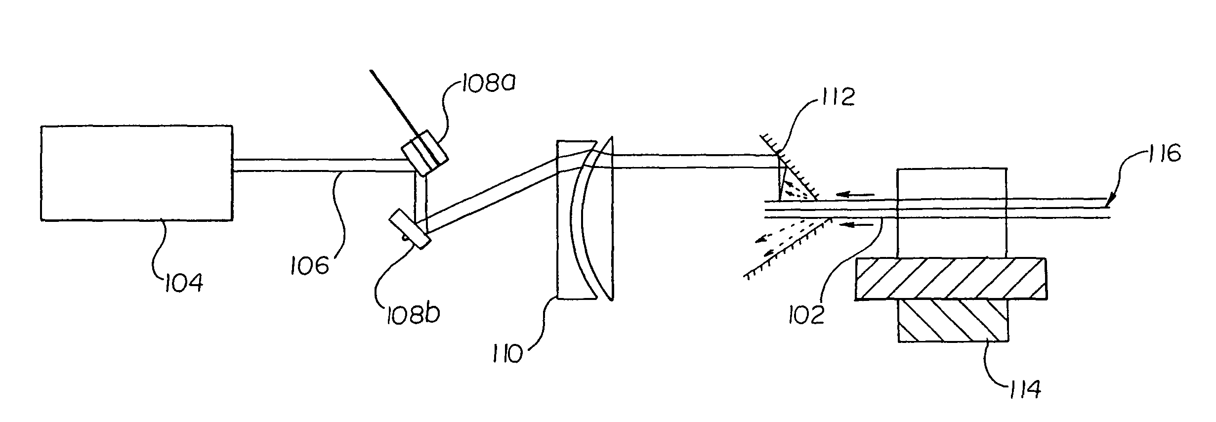
[0031]In one embodiment, the instant invention is directed to a method of manufacturing a stent. The method involves cutting a desired pattern in a tube and comprises the steps of providing a tube having a longitudinal axis therethrough, providing a stationary source of laser radiation, generating a beam of laser radiation using the source of laser radiation, and cutting a desired pattern into the tube by scanning the beam over a desired region of the tube to remove portions of the tube in the desired pattern of the stent and leaving portions of the ...


PUM

PropertyMeasurementUnit
Angleaaaaaaaaaa
Areaaaaaaaaaaa
Biocompatibilityaaaaaaaaaa

Abstract

A stent may be manufactured by providing a tube having a longitudinal axis therethrough, providing a stationary source of laser radiation, generating a beam of laser radiation using the source of laser radiation, and cutting a desired pattern into the tube by scanning the beam over a desired region of the tube.

Description

STATEMENT OF RELATED APPLICATION[0001]This is a continuation of U.S. patent application Ser. No. 10 / 301,984, filed Nov. 22, 2002, entitled “Improved Laser Stent Cutting,” now U.S. Pat. No. 6,696,667.BACKGROUND OF THE INVENTION[0002]Laser cutting of stents has been disclosed in a number of patents including U.S. Pat. Nos. 5,514,154, 5,759,192, 6,131,266 and 6,197,048 and is the preferred technology for stent manufacture in the medical device industry. The conventional approach is to move a hollow tube of metal such as stainless steel under a stationary laser beam. Although the laser is capable of a very rapid cutting speed, the cutting speed of this approach is limited by the speed of the motion drives and in particular the speed of the rotational motor drive.[0003]A typical laser arrangement is shown in FIG. 1. Laser 102 produces a beam 106 which is conditioned as necessary via optical unit 104 and focused into a spot beam which is impinged against hollow tube 108. Hollow tube 108 m...

Claims


Application Information

Patent Timeline
IPC IPC(8): B23K26/00A61F2/06A61F2/90B23K26/06B23K26/08B23K26/10B23K26/38
CPCB23K26/063B23K26/0635B23K26/0807B23K26/0823B23K26/10B23K26/103B23K26/38A61F2/91B23K2203/04B23K26/082B23K26/0622B23K26/0624B23K2103/05
Inventor FLANAGAN, AIDEN
Owner BOSTON SCI SCIMED INC
Why Eureka
Try Eureka