

Light emitting diode (LED) lamp replacement driver for linear fluorescent lamps
a technology of led lamps and electronic ballasts, which is applied in the use of semiconductor lamps, electroluminescent light sources, electric lighting sources, etc., can solve the problems of high labor costs, high risk of fire and shock, and the disposal of fluorescent lamps raises environmental issues
- Summary
- Abstract
- Description
- Claims
- Application Information
AI Technical Summary
Benefits of technology
Problems solved by technology
Method used
Image

Examples
Embodiment Construction
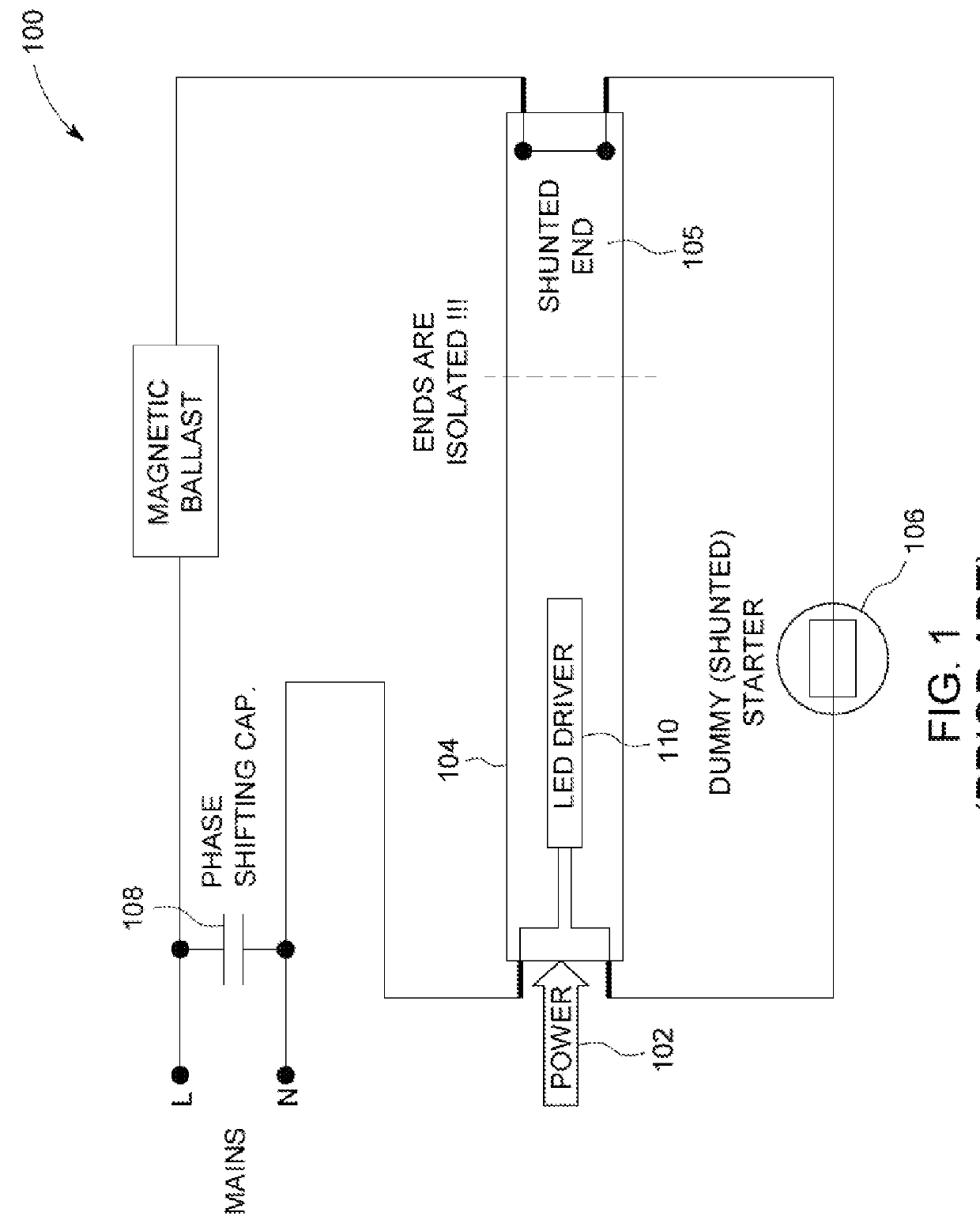
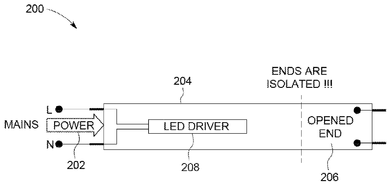
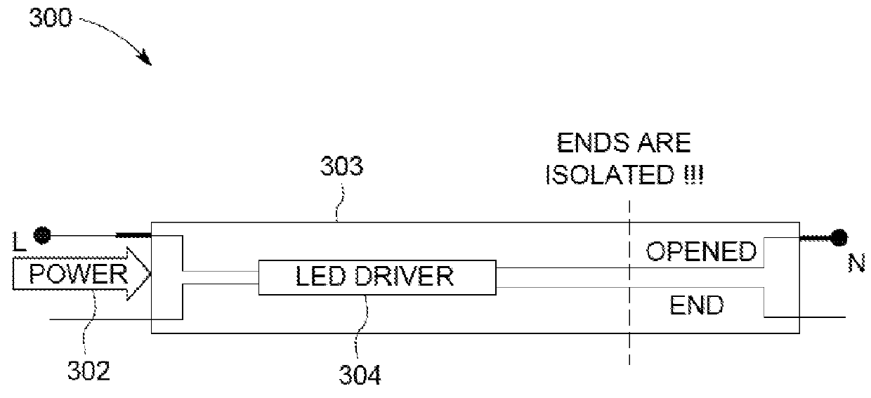
[0014]Given the aforementioned deficiencies, a need exists for methods and systems for a universal, low-cost solution for LFL LED replacement lamps. More particularly, a need exists for methods and systems for LFL LED replacement lamp drivers for electronic ballasts that eliminate the need for significant fixture modification.
[0015]Embodiments of the present invention provide a replacement driver circuit. The driver circuit includes an input port configured for coupling to a ballast and a transformer having a first side coupled to the input port. The driver circuit also includes a rectifier having an input portion coupled to a second side of the transformer and an output portion configured for coupling to a light source. The transformer is configured to match output characteristics of the ballast to input characteristics of the light source.
[0016]As noted above, the illustrious embodiments of the present invention provide a low-cost driver solution for LFL LED replacement lamps for ...
PUM
 Abstract
Description
Claims
Application Information