Refrigeration device for container

a container and refrigeration device technology, applied in the field of refrigeration devices for containers, can solve the problems of reducing the degree of freshness, and achieve the effects of simple structure, low cost and reduced cos

Inactive Publication Date: 2017-09-07
DAIKIN IND LTD
View PDF7 Cites 2 Cited by
  • Summary
  • Abstract
  • Description
  • Claims
  • Application Information

AI Technical Summary

Benefits of technology

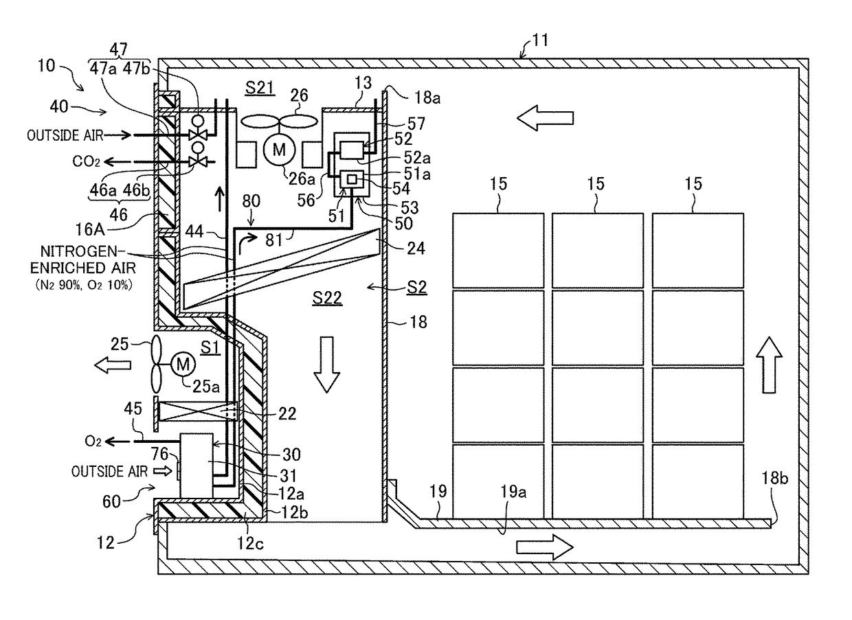
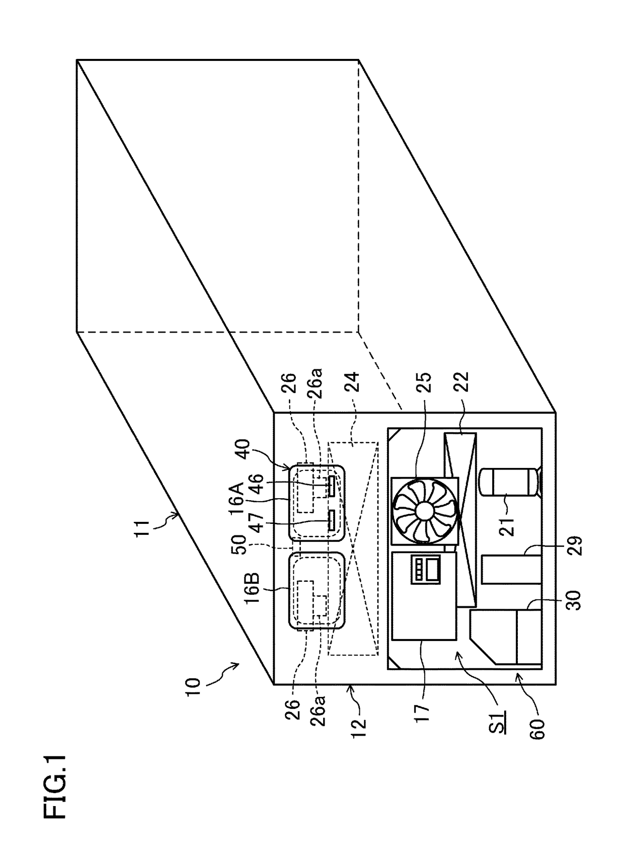
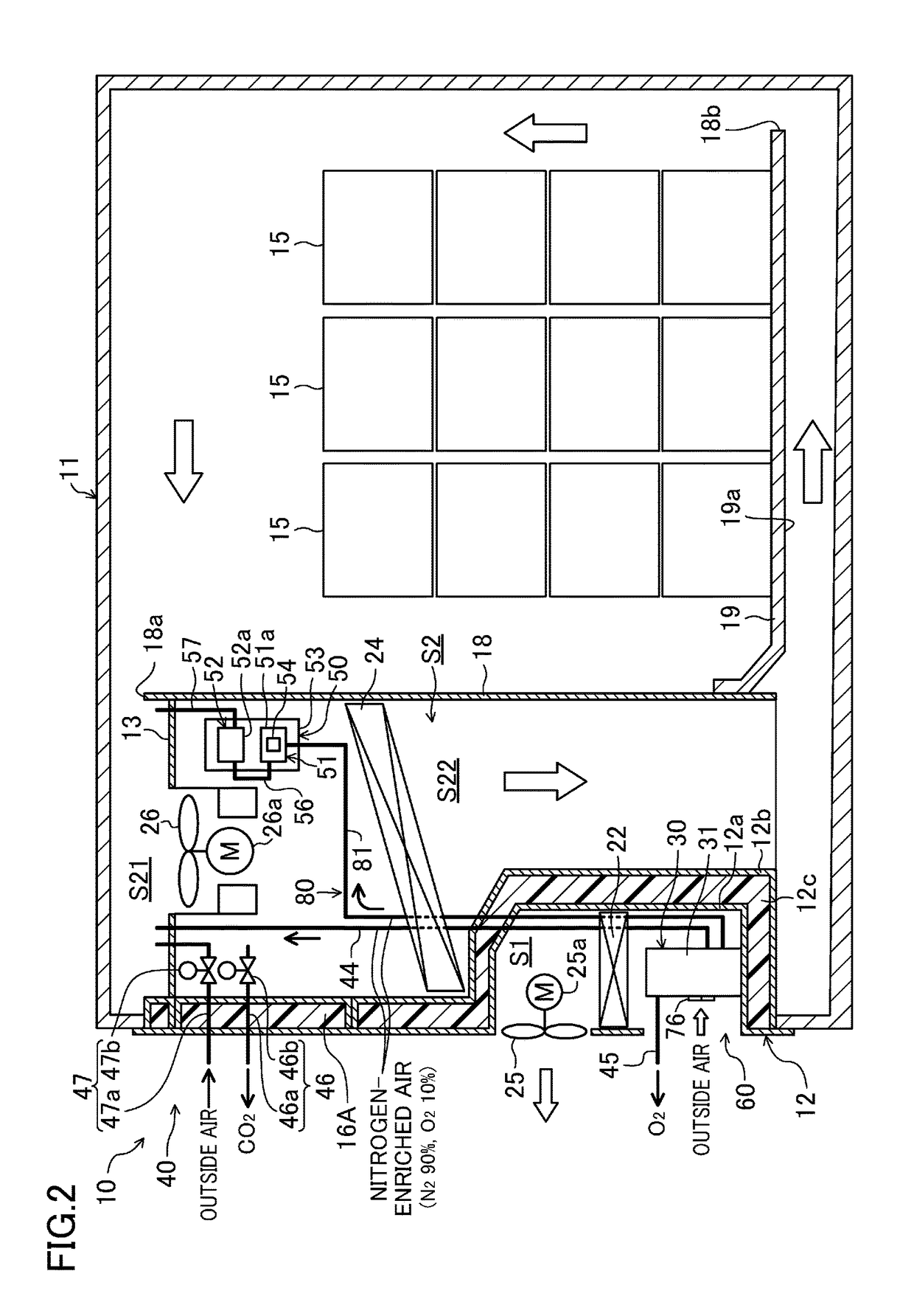
[0026]According to the first aspect, heat generated by the pump mechanism (31P) joins the air flow, and is released through the cooling air outlet port (79b) out of the unit case (70). This air flow is produced by the exterior fan (25) for supplying the outside air to the radiator (22). Thus, while the exhaust tube (85) needs to be provided to solve the problem of heat, an additional component such as a fan does not have to be provided. Thus, the problem of heat generated by the gas supply device (30) may be solved at low cost.
[0027]According to the second aspect, the exhaust tube (85) having a simple structure may define the exhaust passage (85). Thus, the problem of heat generated by the gas supply device (30) may be solved at lower cost.
[0028]According to the third aspect, at least one portion of the exhaust tube (85) is configured as the downwardly extendin

Problems solved by technology

However, since it takes time to reach such a target concentration, the plants will discolor, rot

Method used


Image

  • Refrigeration device for container
  • Refrigeration device for container
  • Refrigeration device for container

Examples


embodiment

Second Variation of Embodiment

[0158]A second variation of the embodiment will now be described. In a container refrigeration apparatus (10) according to the present variation, the shape of a tilted portion (72c) of a unit case (70) of a gas supply device (30) has a different shape from that in the embodiment.

[0159]As illustrated in FIG. 15, one end portion of a top panel (72b) (the left end portion illustrated in FIG. 15) smoothly transits into the tilted portion (72c), which is rounded and tilted so as to descend toward its outer end (its left end illustrated in FIG. 15). Electrical components such as first and second directional control valves (32, 33), a purge valve (36), and a measurement on-off valve (82) are disposed in a space under the tilted portion (72c).

[0160]Also in the container refrigeration apparatus (10) according to the present variation, condensed water produced on the tilted portion (72c) flows along the inner surface of the tilted portion (72c) without dripping d...


PUM


Abstract

Disclosed herein is a container refrigeration apparatus including an exterior fan and a gas supply device. The gas supply device includes a unit case having a cooling air inlet port and a cooling air outlet port, and a pump mechanism housed in the unit case and configured to suck, and compress, outside air. The container refrigeration apparatus has an exhaust passage through which the unit case and a space on a suction side of the exterior fan are connected together such that the exterior fan sucks air through the cooling air outlet port out of the unit case. As a result, the problem of heat generated by the gas supply device including the pump mechanism may be solved at low cost.

Description

TECHNICAL FIELD[0001]The present invention relates to a refrigeration apparatus for a container.BACKGROUND ART[0002]Container refrigeration apparatuses have been used to cool the interior of a container for use in, e.g., marine transportation (see, e.g., Patent Document 1).[0003]The container is loaded with plants such as bananas and avocados. Plants perform respiration by absorbing oxygen in the air and releasing carbon dioxide even after they are harvested. If the oxygen concentration in the container is reduced to a predetermined target concentration as a result of the plant respiration, the respiration rate of the plant decreases. However, since it takes time to reach such a target concentration, the plants will discolor, rot, or deteriorate in other ways in the meantime, which results in a decreased degree of freshness.[0004]To address this problem, a container refrigeration apparatus of Patent Document 1 includes a gas supply device which produces nitrogen-enriched air having ...

Claims


Application Information

Patent Timeline
IPC IPC(8): F25D23/00A23B7/04A23B7/148F25D17/06F25D17/04
CPCF25D23/003F25D17/06F25D17/042B63B25/00A23B7/0425A23V2002/00A23B7/148F25D11/003
Inventor KAMEI, NORITAKAYOKOHARA, KAZUMATANAKA, NAOHIROOZATO, ATSUSHI
Owner DAIKIN IND LTD
Why Eureka
Try Eureka