
Image processing device, image processing method, and recording medium

a technology of image processing and image portion, which is applied in the field of image processing device, image processing method, and recording medium, can solve the problem that users cannot easily operate the intensity of the texture portion as users

Active Publication Date: 2016-07-12
RICOH KK
View PDF26 Cites 2 Cited by
  • Summary
  • Abstract
  • Description
  • Claims
  • Application Information

AI Technical Summary

Benefits of technology

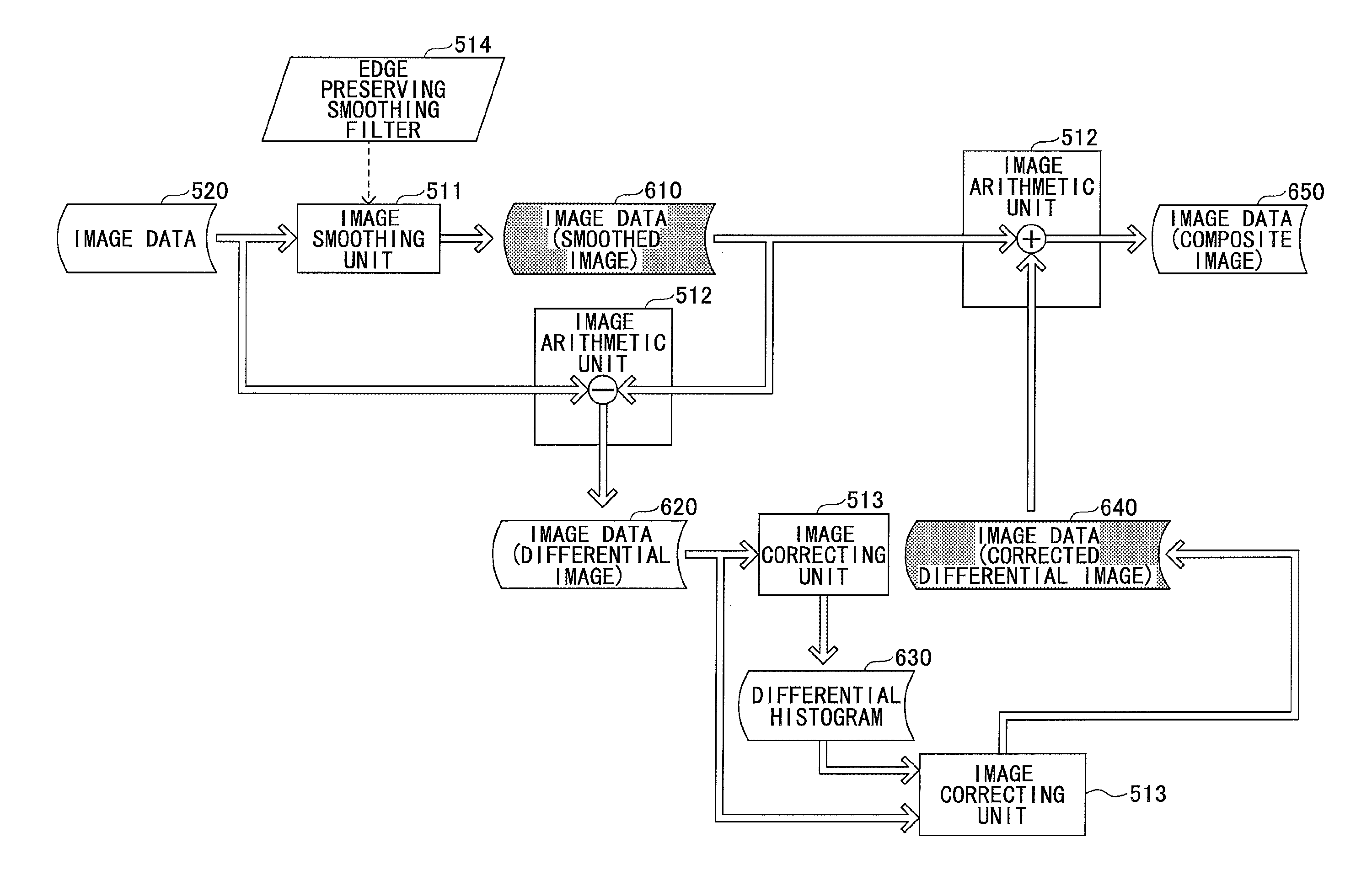
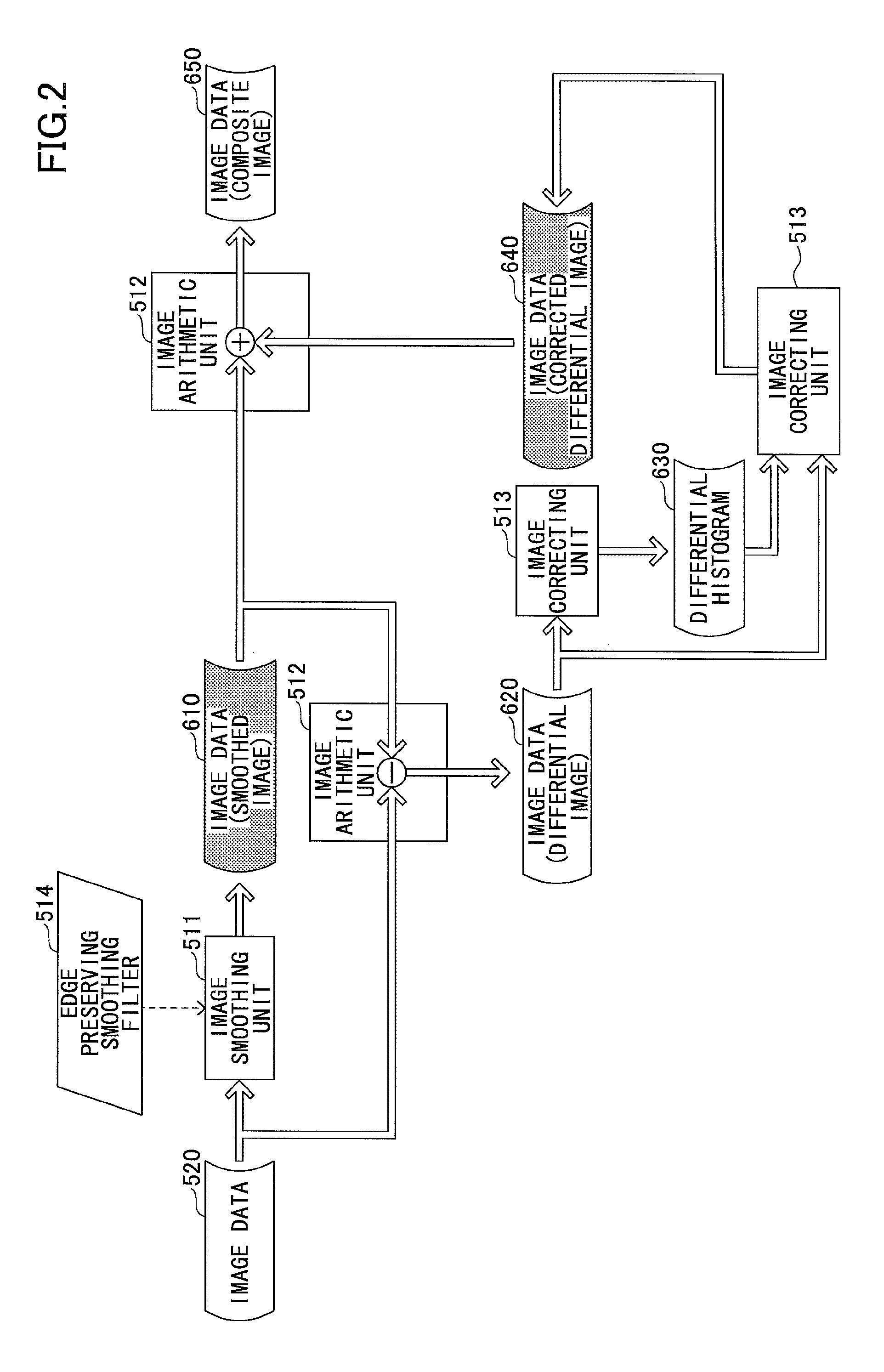
The present technology provides an image processing device, method, and recording medium that can work on the intensity of texture components in an image. The device generates smoothed image data with an edge preserving smoothing filter and generates differential image data between the original image data and the smoothed image data. A histogram is then generated to show the frequencies of difference values in the differential image data. Using this information, the device corrects the first differential image data by calculating a correction amount and then synthesizes the smoothed image data and the second differential image data. This technology allows for improved image quality with reduced blurring and improved texture preservation.

Problems solved by technology

However, in the prior art described above, a user cannot easily operate an intensity of the texture portion as the user desired.

Method used


Image

  • Image processing device, image processing method, and recording medium
  • Image processing device, image processing method, and recording medium
  • Image processing device, image processing method, and recording medium

Examples


first embodiment

[0028](First Embodiment)

[0029]

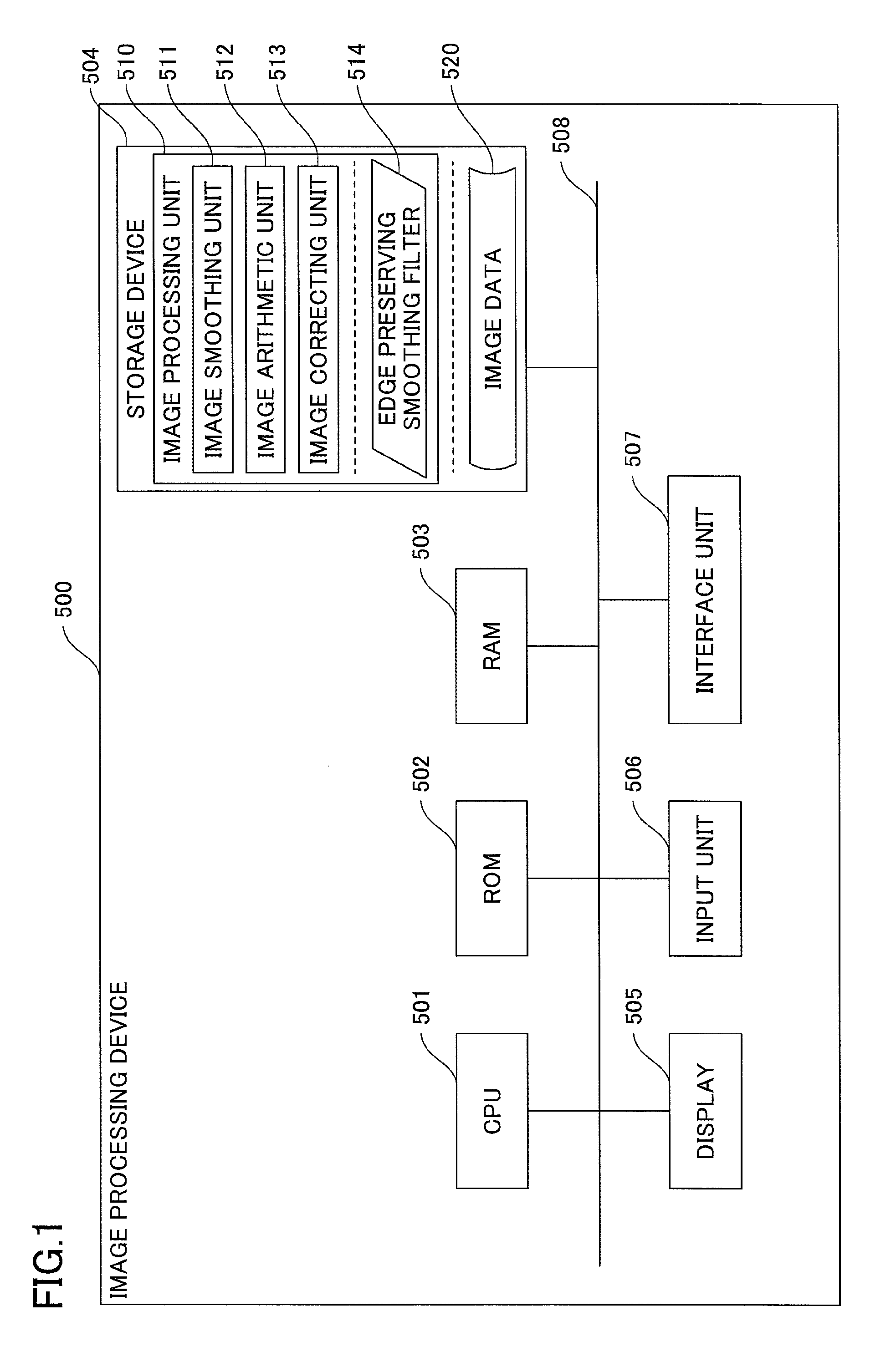
[0030]In the following, an example configuration of an image processing device capable of performing image processing of the present embodiment will be described. FIG. 1 is a block diagram illustrating an example configuration of an image processing device of the first embodiment.

[0031]As described in FIG. 1, the image processing device 500 includes a CPU (Central Processing Unit) 501, a ROM (Read Only Memory) 502, a RAM (Random Access Memory) 503 and a storage device 504. Further, the image processing device 500 includes a display 505, an input unit 506 and an interface unit 507. Additionally, parts in the image processing device 500 are connected with each other through a bus 508.

[0032]The CPU 501 is a processor for executing a program stored in the storage device 504.

[0033]The ROM 502 is a nonvolatile memory. The ROM 502 stores programs, data and the like for enabling the CPU 501 to execute the program stored in the storage device 504. Specifically, ...

second embodiment

[0070][Second Embodiment]

[0071]In the following, an image processing device of the second embodiment will be described. In the present embodiment, correction amount is determined based of a differential histogram given in advance (reference histogram).

[0072]

[0073]First, a functional configuration of the image processing unit 510 of the image processing device 500 will be described. FIG. 4 is a block diagram illustrating the functional configuration of the image processing unit of the image processing device of the second embodiment. Additionally, the difference of the functional configurations of the image processing unit 510 of the image processing device 500 between the present embodiment and the first embodiment (FIG. 2) is a process surrounded by dotted line 800.

[0074]Specifically, the image correcting unit 513 determines the correction amount based on the differential histogram 630 and a differential histogram (reference differential histogram) 530 which is given by the user in...

third embodiment

[0090][Third Embodiment]

[0091]In the following, an image processing device of the third embodiment will be described. In the present embodiment, the correction amount is determined using a cumulative frequency histogram. That is, the correction amount is determined based on a cumulative frequency histogram 631 and a cumulative frequency histogram (reference cumulative frequency histogram) 531 instead of the differential histogram 630 and the reference differential histogram 530 of the second embodiment.

[0092]Additionally, the cumulative frequency histogram (reference cumulative frequency histogram) 531 may be given in advance, or may be generated based on the differential histogram (reference differential histogram) 530 given in advance. Herein below, description will be given where the cumulative frequency histogram (reference cumulative frequency histogram) 531 is given in advance.

[0093]

[0094]First, a functional configuration of the image processing unit 510 of the image processin...


PUM


Abstract

An image processing device includes a first generating unit configured to generate smoothed image data including an edge portion by performing a smoothing process on original image data using an edge preserving smoothing filter; a second generating unit configured to generate first differential image data of a differential image between an image of the original image data and an image of the smoothed image data; a histogram generating unit configured to generate a differential histogram, which is a histogram of frequencies of difference values included in the first differential image data; a third generating unit configured to generate second differential image data by correcting the first differential image data using a correction amount, the correction amount for the first differential image data being calculated based on the differential histogram; and a synthesizing unit configured to synthesize the smoothed image data and the second differential image data.

Description

BACKGROUND OF THE INVENTION[0001]1. Field of the Invention[0002]The present technology relates to an image processing device, an image processing method, and a recording medium.[0003]2. Description of the Related Art[0004]An image can be divided broadly into a flat potion, an edge potion and a texture portion. The flat portion is a region in the image having a small local luminance change while the edge portion is a region in the image having a large local luminance change. The texture portion is a region in the image having a luminance change in a relatively broad area, the luminance change not being so large as that of the edge portion.[0005]A general impression of the image is determined according to the texture portion. When the texture portion included in a region in the image has a large luminance change, the image has a relatively rough impression, while when the texture portion included in a region in the image has a small luminance change, the image has a relatively smooth ...

Claims


Application Information

Patent Timeline
Patent Type & Authority Patents(United States)
IPC IPC(8): G06T5/40G06T5/00
CPCG06T5/40G06T5/004G06T5/75
Inventor NAKAMURA, SATOSHI
Owner RICOH KK
Learn More