Power supply device and method of assembling the power supply device

a power supply device and power supply technology, applied in the field of waterproof power supply devices and a method of assembling the power supply devices, can solve the problems of wearable electronic products that have a longer standby time, battery damage by high-frequency heating energy, etc., and achieve excellent waterproof effect, strengthen the power supply device, and overcome the damage of high-frequency heating energy.

Active Publication Date: 2016-07-19
CHENG UEI PRECISION IND CO LTD
View PDF24 Cites 4 Cited by
  • Summary
  • Abstract
  • Description
  • Claims
  • Application Information

AI Technical Summary

Benefits of technology

[0015]As described above, the power supply device of the present invention utilizes the high-frequency heating to heat the metallic ring for fusion of the cover and the main body close to the metallic ring so as to completely seal up the battery in the main body, so that can achieve an excellent waterproof effect. In order to overcome the damage from the energy of the high-frequency heating on the battery, the metallic plate is located between the battery and the acting parts by the high-frequency heating to separate the energy of the high-frequency heating. Moreover, the metallic plate can strengthen the power supply device to improve security of the power supply device when carrying.

Problems solved by technology

So if the strip body is additionally provided with a battery, the wearable electronic product will have a longer standby time.
However, if the high-frequency heating is applied to the power supply device, namely the water-proof structure of the power supply device is processed by the high-frequency heating for fusion of the cover and the strip body to eliminate the splicing gaps, the battery is apt to be damaged by the energy of the high-frequency heating.

Method used


Image

  • Power supply device and method of assembling the power supply device
  • Power supply device and method of assembling the power supply device
  • Power supply device and method of assembling the power supply device

Examples


Embodiment Construction

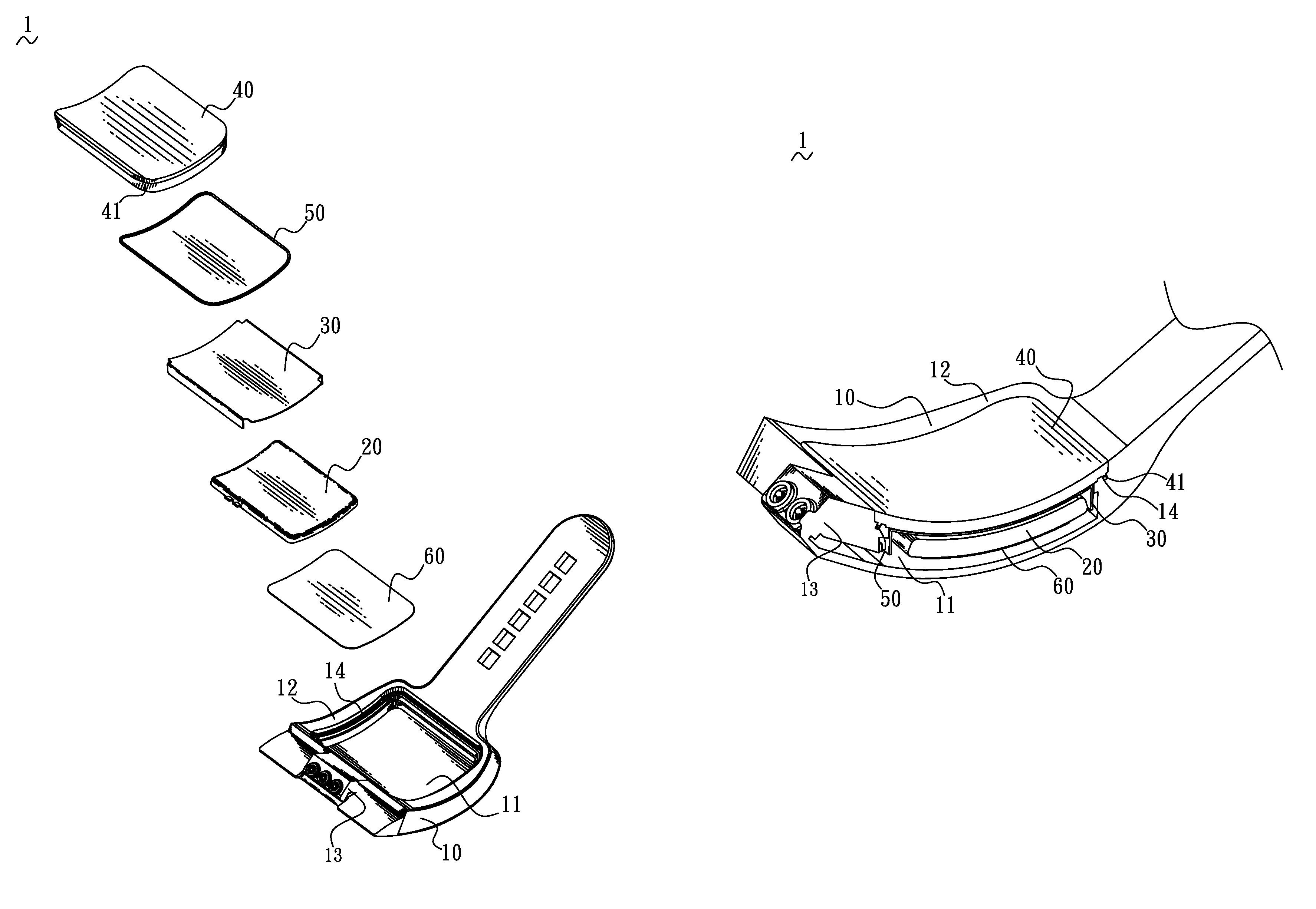
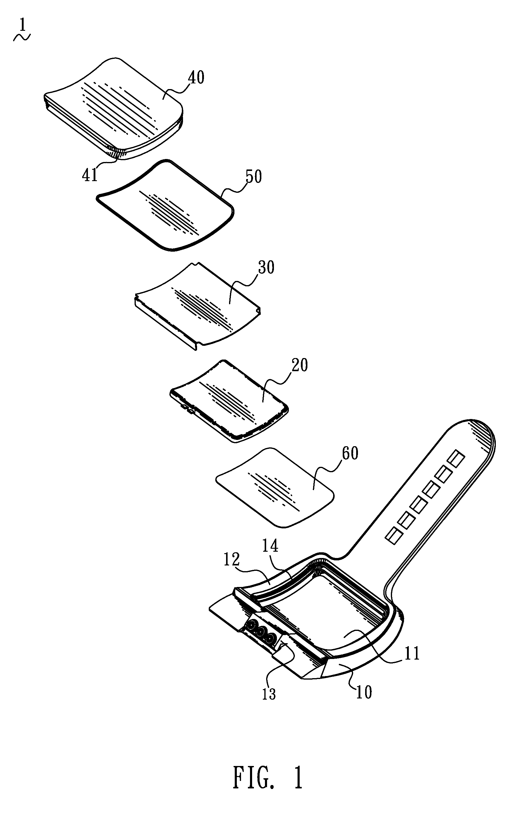
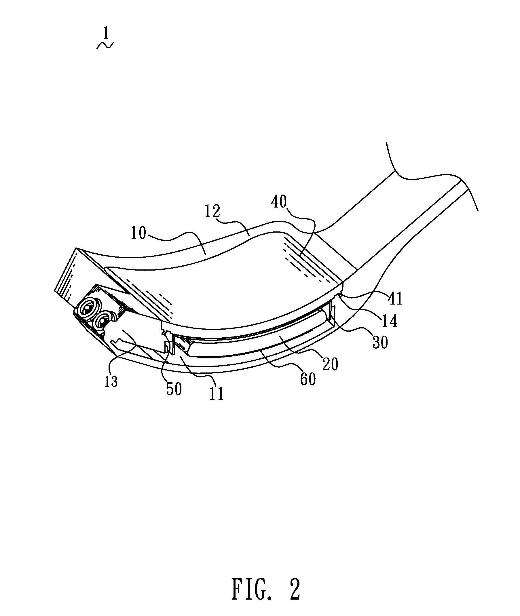
[0022]Referring to FIG. 1 and FIG. 2, a power supply device 1 in accordance with an embodiment of the present invention is adapted to supplying power for an electronic product (not shown). The power supply device 1 includes a main body 10, a battery 20, a metallic plate 30, a cover 40 and a metallic ring 50, wherein the battery 20 and the metallic plate 30 are disposed in the main body 10 and covered by the cover 40, and the metallic ring 50 is positioned between the cover 40 and the main body10.

[0023]The main body 10 is of a flexible strip body and adapted for being worn on the human body. The main body 10 defines a receiving cavity 11 therein. An inner face of the main body 10 abutting against the human body is designated as a contact surface 12 which is a curved surface in this embodiment. The receiving cavity 11 is open through the contact surface 12 to form an opening (not labeled). The main body 10 is provided with a connecting element 13 of which one end is exposed in the rec...


PUM

PropertyMeasurementUnit
poweraaaaaaaaaa
flexibleaaaaaaaaaa
energyaaaaaaaaaa

Abstract

A power supply device includes a main body defining a receiving cavity which has an opening, a battery and a metallic plate both disposed in the receiving cavity, a metallic ring mounted around the opening, and a cover disposed at the opening. The metallic ring is positioned between the cover and the main body and heated by the high-frequency heating for fusion of the cover and the main body to seal up the battery in the receiving cavity. The metallic plate is located between the battery and acting parts by the high-frequency heating to separate the energy of the high-frequency heating from the battery. The main body or the cover are provided with a connecting element of which one end is exposed in the receiving cavity to electrically connect the battery and the other end is exposed outside the power supply device to electrically connect an external electronic product.

Description

CROSS-REFERENCE TO RELATED APPLICATION[0001]The present application is based on, and claims priority from, Taiwan Patent Application No. 103107214, filed Mar. 4, 2014, the disclosure of which is hereby incorporated by reference herein in its entirety.BACKGROUND OF THE INVENTION[0002]1. Field of the Invention[0003]The present invention relates to a power supply device, and more particularly to a water-proof power supply device and a method of assembling the power supply device.[0004]2. The Related Art[0005]At present, a fastening structure used to wear a wearable electronic product on the human body mostly chooses a strip body in addition to spectacle frame, because the strip body is fit for being fixed to limbs of the human body by virtue of flexibility and resilience.[0006]To cope with the increasing power consumption, the battery capacity of the wearable electronic product becomes crucial that will affect the wearable electronic product on the market's popularity.[0007]So if the s...

Claims


Application Information

Patent Timeline
Patent Type & Authority Patents(United States)
IPC IPC(8): B23K1/002H02J7/00G04C10/00H01M2/10H01M2/02H01M50/107H01M50/202H01M50/247
CPCB23K1/002G04C10/00H01M2/1022H02J7/0068H01M2/1094H01M2002/0205H02J7/0063Y02E60/10H01M50/24H01M50/247H01M50/107H01M50/202H02J7/00
Inventor LEE, JAMES CHENG
Owner CHENG UEI PRECISION IND CO LTD
Why Eureka
Try Eureka