Terminal block wiring device

a technology of wiring device and terminal block, which is applied in the direction of coupling device connection, electrical apparatus, connection, etc., can solve the problems of terminal block damage, avoid the disadvantage of screwdriver damage, and facilitate the wiring operation

Active Publication Date: 2016-07-19
DINKLE ENTERPRISE CO LTD
View PDF9 Cites 18 Cited by
  • Summary
  • Abstract
  • Description
  • Claims
  • Application Information

AI Technical Summary

Benefits of technology

[0007]The present invention is to provide a terminal block wiring device, so a wiring operation is provided with effects of fast, convenience and labor saving, and an advantage of allowing the wiring efficiency to be increased is also provided.
[0010]In comparison with related art, the present invention has advantageous features as follows: the wiring jig and the terminal block provided by the present invention can be operated by one hand, and another hand can process a wiring operation (for example inserting a cable), so an advantage of facilitating the wiring operation is provided; in addition, the operation of the wiring jig provided by the present invention is able to save the conventional jig (used for the insulation seat) and the screwdriver required in the conventional terminal block, so a disadvantage of the terminal block being damaged by the screwdriver can be avoided; moreover, the leverage principle is adopted in the wiring jig provided by the present invention, so the first positioning protrusion formed on the handgrip can be served as a pivot, thereby enabling the hook arm to drive the pull member to press the positioning elastic sheet, so a labor-saving wiring operation is provided; furthermore, when no wiring operation is required, the wiring jig can still be fastened on the terminal block without interfering the normal operation of the terminal block, so the wiring jig is prevented from being lost and able to be directly used after being removed from the terminal block, so advantages of convenient and more practical in used are provided.

Problems solved by technology

During the wiring operation for the terminal block, a jig and the screwdriver are required, so the assembly is relatively inconvenient; moreover, if the screwdriver is not properly operated, the terminal block may be damaged.

Method used


Image

  • Terminal block wiring device
  • Terminal block wiring device
  • Terminal block wiring device

Examples


Embodiment Construction

[0019]Preferred embodiments of the present invention will be described with reference to the drawings.

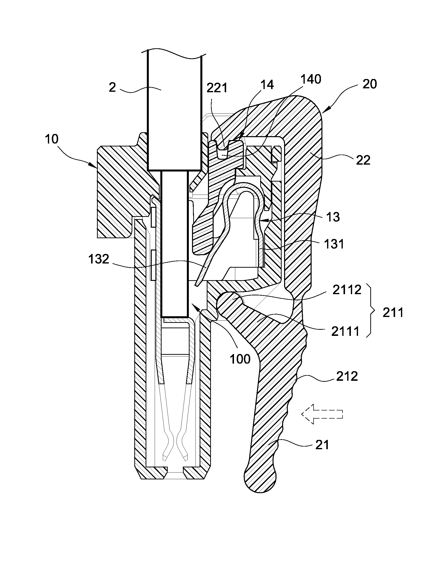
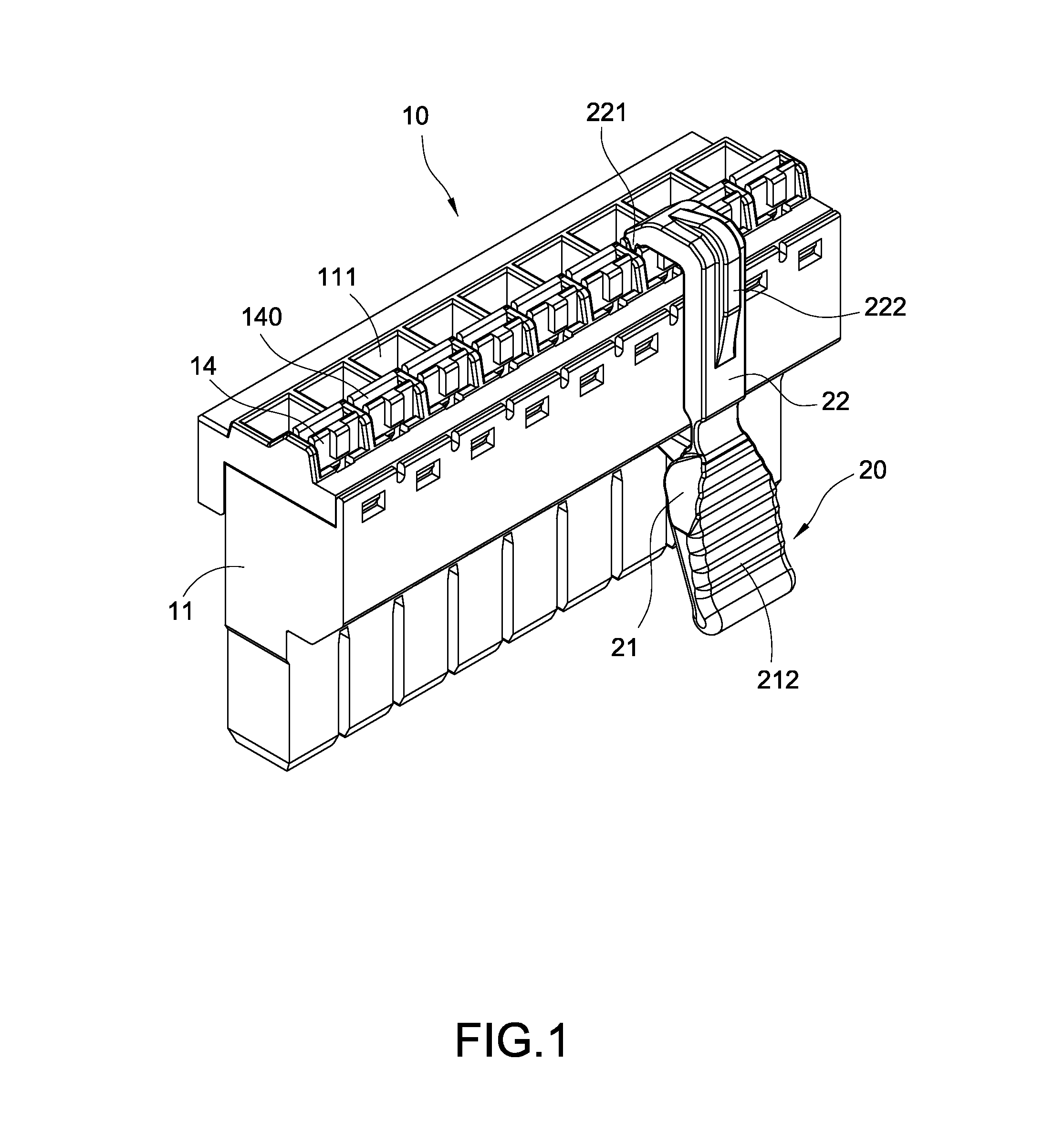
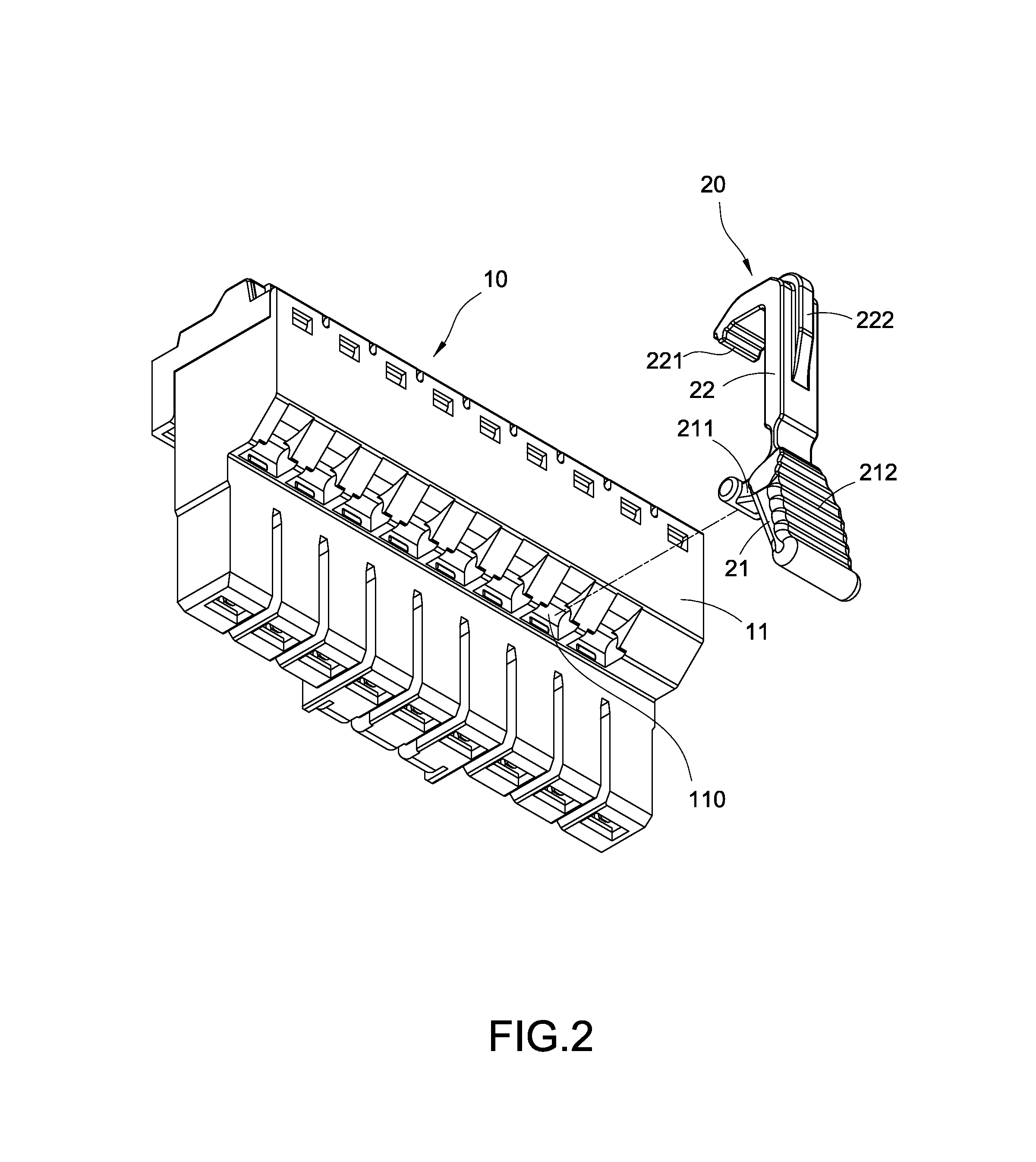
[0020]Please refer to FIG. 1 to FIG. 3, wherein are a perspective exploded view, a perspective view and a cross sectional view showing the assembly of the wiring device according to one preferred embodiment of the present invention. The present invention provides a terminal block wiring device, which includes a terminal block (10) and a wiring jig (20). When a wiring operation is desired to be processed, the wiring jig (20) is positioned on the terminal block (10), and an external force is applied to the wiring jig (20) for enabling the wiring jig (20) to assist the process of electrical conduction. On the other hand, if no wiring operation is required, the wiring jig (20) can still be fastened on the terminal block (10) without interfering the normal operation of the terminal block (10), so the wiring jig (20) is able to be prevented from being lost and able to be directly used aft...


PUM


Abstract

A terminal block wiring device includes a terminal block and a wiring jig (20, 20a). The wiring jig includes a handgrip (21, 21a) and a hook arm (22, 22a), the handgrip (21, 21a) is formed with a first positioning protrusion (211, 211a), the hook arm (22, 22a) is formed with a second positioning protrusion (221, 221a), the wiring jig (20, 20a) is able to be positioned on a terminal block (10, 10a) through the first positioning protrusion (211, 211a) and the second positioning protrusion (221, 221a); when an external force is applied and the first positioning protrusion (211, 211a) is served as a pivot, a cable (2) is enabled to be rapidly inserted and electrically connected to an electric conductive terminal (12), so effects of fast, convenience and labor saving of the wiring operation can be achieved, and the wiring efficiency can also be increased.

Description

BACKGROUND OF THE INVENTION[0001]1. Field of the Invention[0002]The present invention relates to a jig, especially to a terminal block wiring device.[0003]2. Description of Related Art[0004]A terminal block is a composed of an insulation seat and electric conductive components so as to form an electrically conducting device used as a platform allowing a plurality of wires to be electrically connected. The terminal block is widely applied in various fields, such as being applied in an electronic device (for example an air conditioner, a refrigerator, a washing machine or an oven), or a mechanical equipment (for example an industrial computer, an uninterruptible power system or a power supply), or an engineering control equipment (for example an electromechanical system, a refrigerating air conditioner or a programmable controller) or other devices.[0005]In a conventional terminal block, at least one elastic sheet is installed for fastening at least one cable, and the conventional wir...

Claims


Application Information

Patent Timeline
Patent Type & Authority Patents(United States)
IPC IPC(8): H01R13/00H01R13/631
CPCH01R13/631H01R4/48455H01R4/48365
Inventor WU, SHANG-TSAI
Owner DINKLE ENTERPRISE CO LTD
Why Eureka
Try Eureka