Cable holding assembly for cable stapler

a technology of holding assembly and cable stapler, which is applied in the field of cable staplers, can solve the problems of increasing the cost of ownership, the inability of the cable holding piece to hold the cable steadily and reliably, and the inability of the cable holding piece to function, so as to reduce the cost of ownership and increase the efficiency of cabling

Inactive Publication Date: 2007-11-06
POWER PROD
View PDF8 Cites 9 Cited by
  • Summary
  • Abstract
  • Description
  • Claims
  • Application Information

AI Technical Summary

Benefits of technology

[0007]The primary purpose of the present invention is to provide a cable holding assembly for cable staplers to fit cables of different gauges so as to reduce the cost of ownership and to increase the cabling efficiency.
[0009]The protruding cable holding end of the holder blade therefore can be used to hold down the cable reliably before firing a staple to fasten the cable into the wall or the floor. As such, instead of preparing different cable staplers, the present invention allows a single cable stapler to handle cables of various gauges by switching the holder blades.

Problems solved by technology

The cable holding piece of a cable stapler therefore cannot function as expected if its U-shaped notch does not match the gauge and cross-sectional shape of the cable being fixed.
If the cable is too thin or too thick, the cable holding piece cannot hold the cable steadily and reliably.
This not only adds to the cost of ownership but also reduces the cabling efficiency as multiple cable staplers have to be carried and swapped during the work.

Method used


Image

  • Cable holding assembly for cable stapler
  • Cable holding assembly for cable stapler
  • Cable holding assembly for cable stapler

Examples


Embodiment Construction

[0022]The following descriptions are of exemplary embodiments only, and are not intended to limit the scope, applicability or configuration of the invention in any way. Rather, the following description provides a convenient illustration for implementing exemplary embodiments of the invention. Various changes to the described embodiments may be made in the function and arrangement of the elements described without departing from the scope of the invention as set forth in the appended claims.

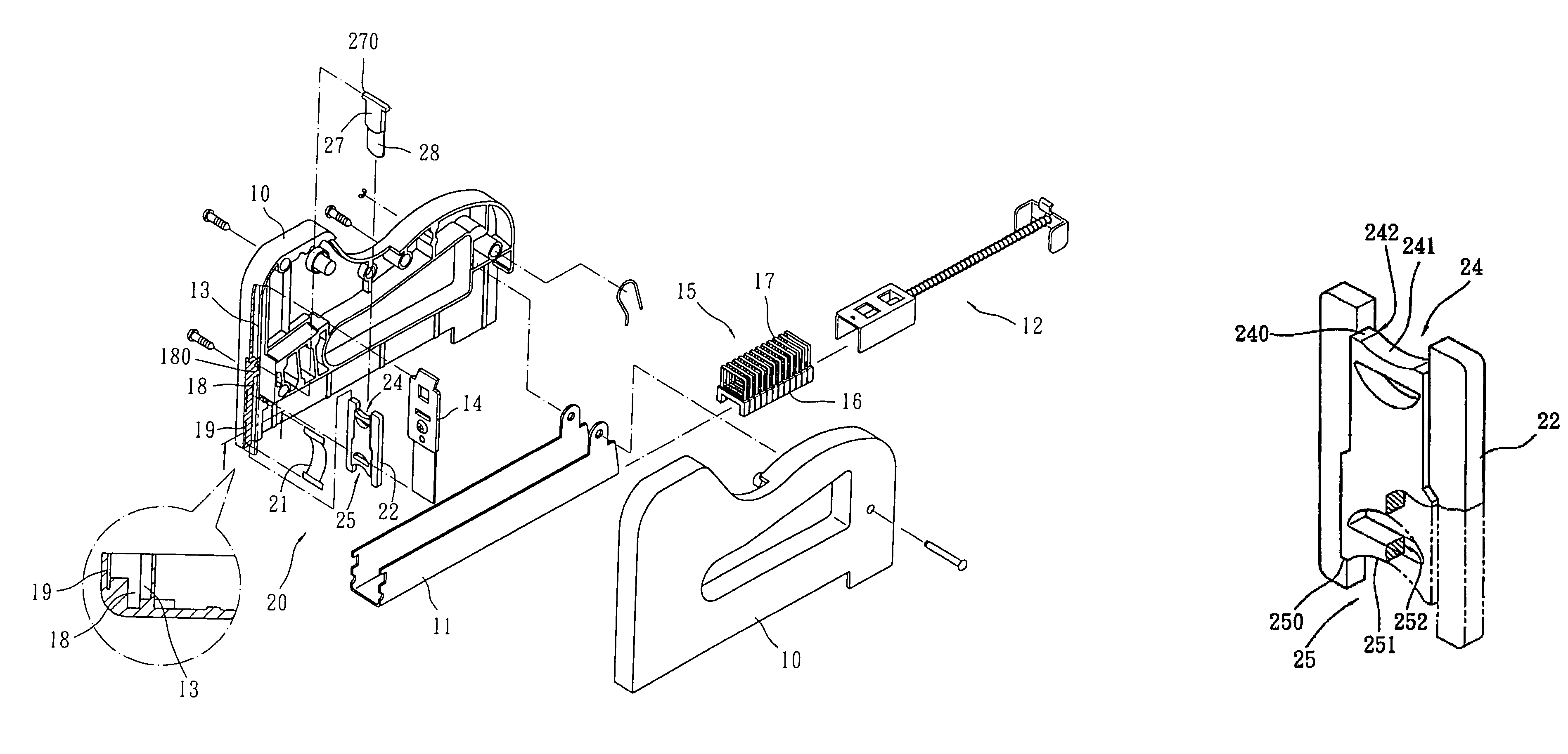
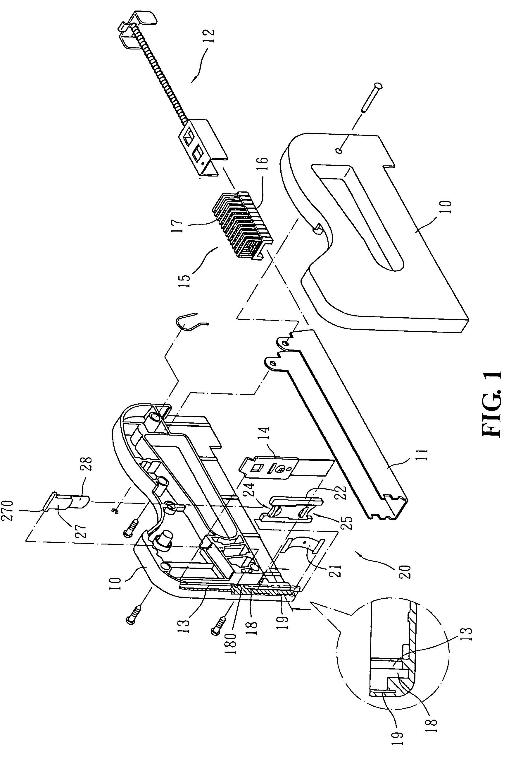
[0023]As shown in FIG. 1, a cable stapler has a hollow case formed by joining two correspondingly shaped casing pieces 10. Inside and at the bottom of the hollow case, an elongated magazine 11 having U-shaped cross-section is provided for accommodating an array of staples 15. Each of the staples 15 has a cable retaining body 16 and a built-in, inverted U-shaped nail 17 penetrating through the body 16. A spring-loaded pusher 12 is slidably configured at one end inside the magazine 11 to advance th...


PUM


Abstract

A cable holding assembly for cable staplers is provided, which is housed inside a slot in front of the muzzle of a cable stapler. The cable holding assembly contains a spring blade, a holder blade, and a resistance blade. The spring blade is configured on the wall of the slot to position the holder blade inside the slot but flexible enough to allow the holder blade to be removed and inserted. The holder blade is H-shaped, forming a first cable holding end and a second holding end at the top and the bottom for cables of different gauges respectively. When the holder blade is inserted into the slot, the bottom end of the resistance blade is pressed against the arched edge of the cable holding end at the top so that the other cable holding end is extended outside of the slot and the cable stapler for holding down the cable reliably.

Description

BACKGROUND OF THE INVENTION[0001](a) Technical Field of the Invention[0002]The present invention generally relates to cable staplers, and more particularly to a cable holding assembly for cable staplers.[0003](b) Description of the Prior Art[0004]When laying out power cables, telephone cables, network cables, or similar flexible cables, a certain kind of cable retainers are usually employed to fix the cables along their paths. The cable retainer usually contains a body having a cable groove at the bottom and a built-in nail for securing the body to the wall or floor, confining the cable inside the groove of the body. To increase the efficiency of cabling, there are also specialized cable staplers that directly punch specially configured staples to fix the cables to the wall or floor. Such a stapler usually has an inverted U-shaped cable holding piece in front of the muzzle to hold down the cable before firing a staple to fasten the cable.[0005]However, cables have different gauges. ...

Claims


Application Information

Patent Timeline
Patent Type & Authority Patents(United States)
IPC IPC(8): B25C5/00
CPCB25C5/06
Inventor CHENG, LI-JUNG
Owner POWER PROD
Why Eureka
Try Eureka