Wiring verification method and device for transformer substation

A verification method and a technology of a verification device, which are applied in the field of substation wiring verification methods and devices, can solve problems such as inability to guarantee record judgment, comprehensive absolute correctness, complex wiring of large-scale substations, and maintenance delays, etc., to achieve load testing and verification Fast real-time, time-reducing effects

Active Publication Date: 2015-03-25
STATE GRID HUNAN ELECTRIC POWER +2
View PDF6 Cites 9 Cited by
  • Summary
  • Abstract
  • Description
  • Claims
  • Application Information

AI Technical Summary

Problems solved by technology

However, in the process of restoring wiring, the maintenance (pre-test) work is often delayed due to wiring errors. To solve this problem, the planned working time is usually increased to reserve time for handling wiring errors. After manual verification and recording, And after making the conclusion that the wiring is correct, the power transmission can be resumed
However, for large substations, due to the complex wiring of large substations, it takes too much time to verify the correctness of the wiring, and can even run through 1 / 3 of the entire maintenance (pre-test) planning time, so this method is not suitable for large substations Especially the work of the hub station
To sum up, the current commonly used correct method of verifying wiring is too time-consuming, and can even run through 1 / 3 of the entire planned time, and due to manual operation, the absolute correctness of recording, testing wiring, judgment, and synthesis cannot be guaranteed

Method used


Image

  • Wiring verification method and device for transformer substation
  • Wiring verification method and device for transformer substation
  • Wiring verification method and device for transformer substation

Examples


Embodiment Construction

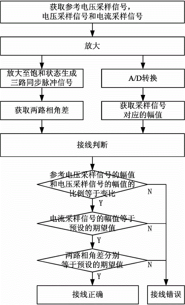
[0025] Such as figure 1 As shown, the steps of the wiring verification method used in the substation of this embodiment include:

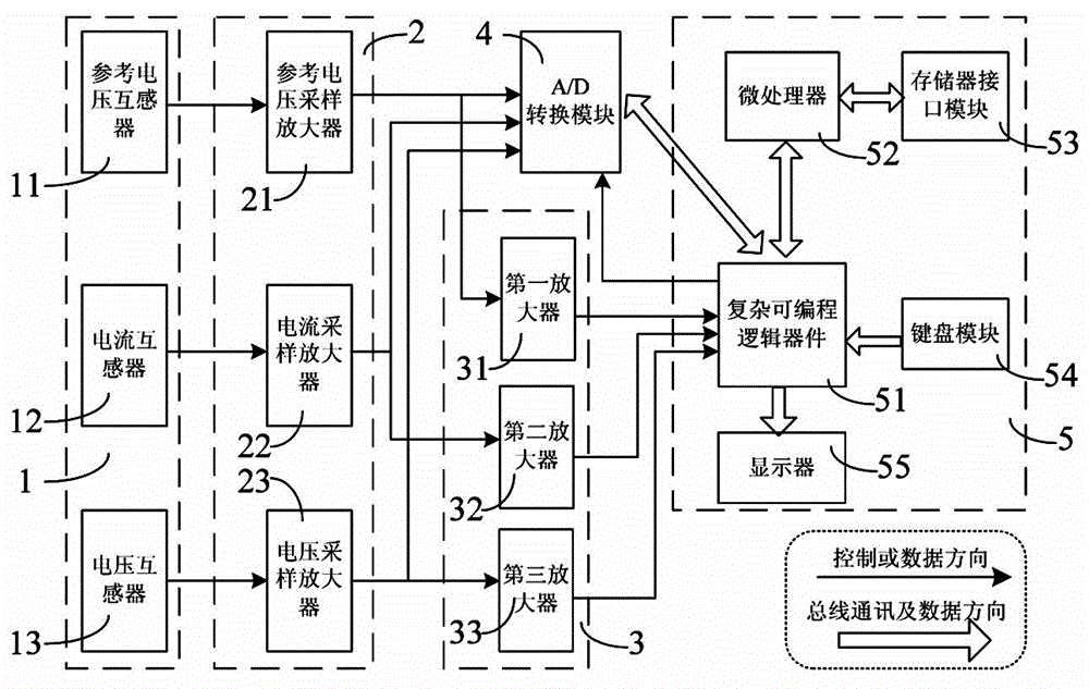
[0026] 1) Obtain the reference voltage sampling signal of the corresponding bus of the verified secondary device, and obtain the voltage sampling signal and current sampling signal of the verified secondary device;

[0027] 2) Amplify the acquired sampling signals in sequence;

[0028] 3) Perform A / D conversion on the amplified reference voltage sampling signal, voltage sampling signal, and current sampling signal, respectively, and perform fast Fourier transform calculation on the sampling signal obtained after A / D conversion to obtain the corresponding amplitude;

[0029] 4) Amplify the amplified reference voltage sampling signal, voltage sampling signal, and current sampling signal to the saturation state to generate three synchronization pulse signals, and obtain the phase angle difference of two of the three synchronization pulse signals;

[0030] 5) De...


PUM


Abstract

The invention discloses a wiring verification method and device for a transformer substation. The method comprises the steps of collecting reference voltage sampling signals and voltage sampling signals and current sampling signals of a verified secondary device, obtaining phase angle differences of every two of the three routes of sampling signals, determining that wiring of the verified secondary device is correct when it is judged that the proportion of the amplitude of the reference voltage sampling signals and the amplitude of the voltage sampling signals is equal to the ratio of transformation of the transformer substation, the amplitude of the current sampling signals is equal to a preset expected value and the phase angle differences of every two of the three routes of sampling signals are equal to preset expected values respectively, and otherwise, determining that wiring of the secondary device is wrong. The device comprises a sensor unit, an amplifying unit, a synchronous generation circuit, an A/D conversion module and a control unit. Whether wiring of the secondary device of the transformer substation is correct can be automatically judged and recorded, duration time of overhaul (prerun) is reduced, wiring verification speed is high, consumed time is little, and judging correctness is high.

Description

Technical field [0001] The invention relates to auxiliary equipment used in the maintenance (pre-test) of secondary equipment in a substation, and in particular to a wiring verification method and device for the substation. Background technique [0002] In the existing technology, the maintenance (pre-test) of the secondary equipment of the substation generally requires the disconnection of the wiring first, and then the accuracy, operating time, and operating amplitude of the secondary equipment are tested. However, in the process of restoring the wiring, the maintenance (pre-test) work is often delayed due to wiring errors. To solve this problem, the planned working time is usually increased to allow time for handling wiring errors. After manual verification and recording, After the conclusion that the wiring is correct, the power supply can be restored. But for large-scale substations, due to the complicated wiring of large-scale substations, it takes too much time to verify ...

Claims


Application Information

Patent Timeline
Patent Type & Authority Applications(China)
IPC IPC(8): G01R31/02
Inventor 宁志毫张斌钟智
Owner STATE GRID HUNAN ELECTRIC POWER
Why Eureka
Try Eureka