Maximum power point tracking for photovoltaic power generation system

a photovoltaic power generation and maximum power point technology, applied in transmission systems, input/output to record carriers, instruments, etc., can solve the problems of large power loss, inability to reliably use the mppt method for applications with multiple local maximum power points,

Inactive Publication Date: 2016-07-19
MITSUBISHI ELECTRIC RES LAB INC
View PDF9 Cites 9 Cited by
  • Summary
  • Abstract
  • Description
  • Claims
  • Application Information

AI Technical Summary

Problems solved by technology

However, those MPPT methods are not reliable for applications with multiple local maximum power points.
Considerable power loss can be incurred when a local maximum power point is tracked instead of the global maxi mum power point.

Method used


Image

  • Maximum power point tracking for photovoltaic power generation system
  • Maximum power point tracking for photovoltaic power generation system
  • Maximum power point tracking for photovoltaic power generation system

Examples


Embodiment Construction

[0027]Various embodiments of the invention are based on a realization that a voltage of a photovoltaic array at a maximum power point (MPP) can be estimated. The estimated MPP is not necessarily a global MPP, but is sufficiently close to the global MPP, such that an output of a maximum power point tracking (MPPT) performed near the estimated MPP is the global MPP, and not a local MPP. Thus, the estimation of the MPP allows using MPPT under multiple local maximum power points conditions.

[0028]Thus, a MPPT method according to some embodiments of the invention estimates a voltage of the photovoltaic array at the MPP and tracks the maximum power point based on the estimated voltage. The MITT method of those embodiments is suitable for multiple local maximum power points conditions.

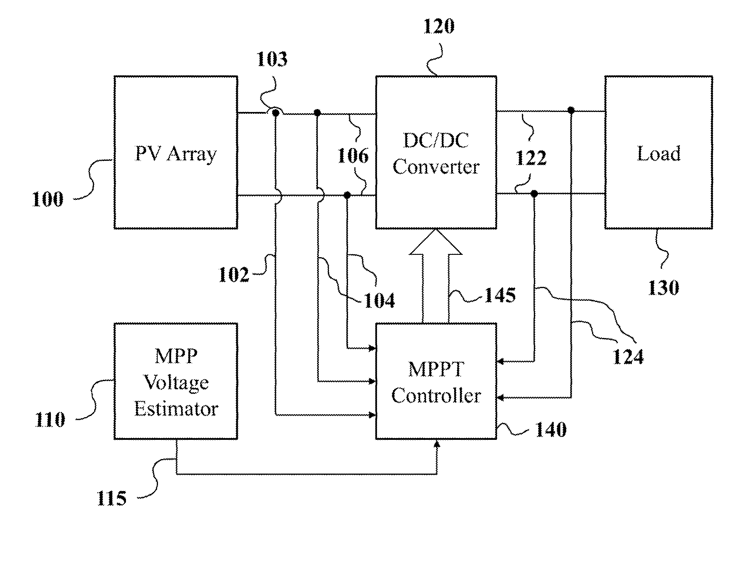
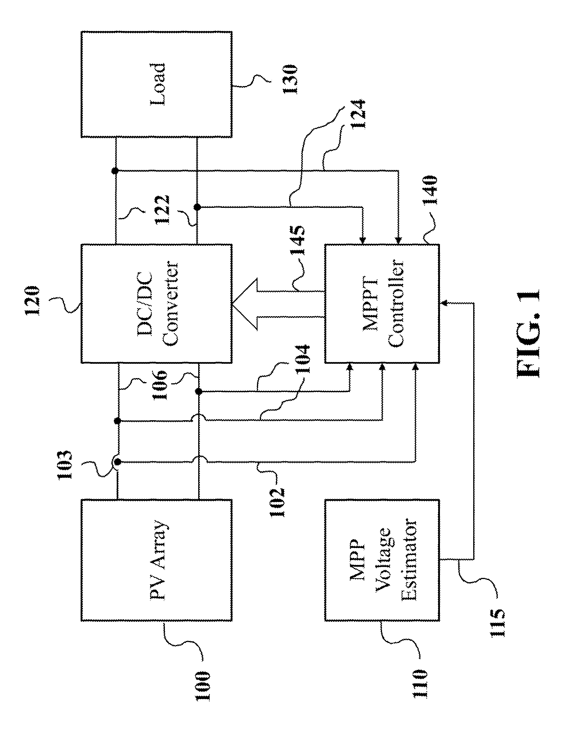
[0029]FIG. 1 shows an example of a photovoltaic power conversion system with MPPT control according to some embodiments of the invention. Voltage of the photovoltaic array 100 is supplied on input lines 106 to...


PUM


Abstract

A method controls power generated by a photovoltaic array. The method estimates a voltage corresponding to a global maximum power point (MPP) of the power generated by the photovoltaic array to produce an estimated voltage; and tracks an output of the power based on the estimated voltage to determine the global MPP.

Description

FIELD OF THE INVENTION[0001]This invention relates generally to electrical power conversion systems, and more particularly to control methods for photovoltaic power conversion system.BACKGROUND OF THE INVENTION[0002]Maximum Power Point Tracking (MPPT) is an electronic system that enables photovoltaic (PV) modules to deliver the maximum available power. MPPT is frequently used by PV power conversion system in conjunction with mechanical tracking that physically moves the modules. For example, a perturb and observe (P&O) MPPT method is described by N. Femia, et al., “A Technique for Improving. P&O MPPT Performances of Double-Stage Grid-Connected Photovoltaic Systems,” IEEE Trans. Ind. Electron., vol. 56, no. 11, pp. 4473-4482. November 2009. The incremental conductance (INC) MPPT is described by F. Liu, et al., “A Variable Step Size INC MPPT Method for PV Systems,” IEEE Trans. Ind. Electron., vol. 55, no. 7, pp. 2622-2628, July 2008. A fractional open-circuit voltage based MPPT is des...

Claims


Application Information

Patent Timeline
Patent Type & Authority Patents(United States)
IPC IPC(8): G06F3/06H02J3/38G05F1/67
CPCH02J3/385G05F1/67Y02E10/58Y10T307/549Y02E10/56
Inventor TEO, KOON HOODENG, YI
Owner MITSUBISHI ELECTRIC RES LAB INC
Why Eureka
Try Eureka