
Electrical conduction block implant device

a technology implant device, which is applied in the field of electric conduction block implant device, can solve the problems of abnormal heart rhythm, blood pooling and even clotting inside the atrium, and can be very serious, and achieve the effect of blocking aberrant electrical signals in safe and effective ways

Inactive Publication Date: 2016-07-26
SYNTACH AG
View PDF229 Cites 25 Cited by
  • Summary
  • Abstract
  • Description
  • Claims
  • Application Information

AI Technical Summary

Benefits of technology

The present invention provides a minimally invasive device and technique for safely and effectively blocking aberrant electrical signals at or near the ostium of the pulmonary veins. It is easy to deploy and has a low risk of complication. Additionally, it consistently creates a circumferential scar line around the pulmonary ostium to completely block aberrant electrical signals causing atrial fibrillation.

Problems solved by technology

When the normal sequence of electrical impulses changes or is disrupted, the heart rhythm often becomes abnormal.
When this happens, the heart is unable to discharge all of the blood from the heart's chambers thus creating a situation where the blood may begin to pool and even clot inside the atrium.
Such clotting can be very serious insofar as the clot can break away from the atrial chamber and block an artery in the brain, and thereby cause a stroke in the individual.
Although the “maze” procedure has its advantages, in practice it can be a complicated and a particularly risky procedure to perform since the surgeon is making numerous physical incisions in the heart tissue.
Although ablation catheter procedures remain less invasive than previous surgical methods like the “maze” procedure, they nevertheless retain a significant element of risk.
For example, ablation procedures often utilize high power RF energy or ultrasonic energy, which may adequately create electrical block, but their inherent destructive nature allows for the possibility of unintended damage to the target tissue or nearby areas.
Further, it is often difficult to achieve certainty as to whether the appropriate amount of ablation has been performed uniformly around the perimeter of the target site or if the desired site is even being ablated.
This is a serious complication and as a result, many doctors try to limit their treatment to the ostium of the pulmonary veins to minimize the risk of creating a stenosis in the pulmonary veins.
The solutions in the prior art, however, are not believed to be entirely effective in many cases, and indeed may result in actually inducing long term arrhythmias and inefficacy.

Method used


Image

  • Electrical conduction block implant device
  • Electrical conduction block implant device
  • Electrical conduction block implant device

Examples


Embodiment Construction

[0074]The ostium of the pulmonary veins has a highly variable geometry from one patient to another and this presents difficulty in reliably treating atrial arrhythmias using previous methods. That is, the variable geometry has in the past made it difficult to reliably create a continuous line of electrical block around the perimeter of the ostium in each and every patient.

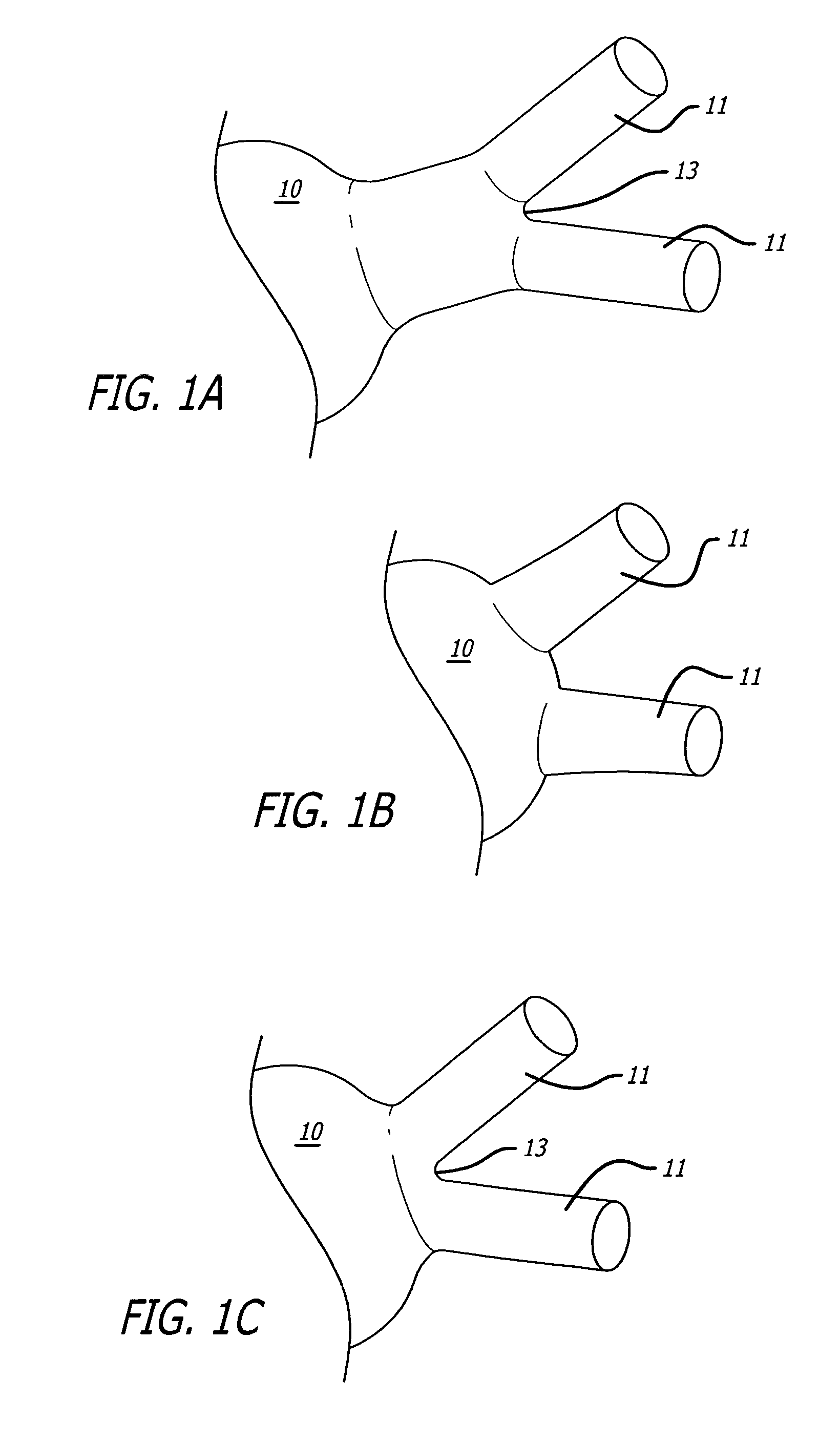
[0075]In illustration of this point, FIGS. 1A-1C present three ostium geometries that can occur in the general human population. These Figures show a left atrium 10 of a human heart wherein two adjacent pulmonary veins 11 may originate directly from two ostia in the left atrium (FIG. 1B) or may originate from one ostia in the left atrium followed by a bifurcation 13 downstream of the left atrium. Moreover, the bifurcation 13 may be located near the left atrium (FIG. 1A) or far from the left atrium (FIG. 1C). Finally, various hybrids of these geometries are also possible as some people can have more or less than the...


PUM


Abstract

The present invention provides an electrical block implant sized and shaped for securement at the perimeter of the pulmonary ostium of the left atrium. By utilizing various expandable ring designs and optional anchoring mechanisms, the present invention causes even, circular scarring around the perimeter of the pulmonary ostium, achieving reliable blocking of aberrant electrical signals responsible for atrial fibrillation.

Description

RELATED APPLICATIONS[0001]This application claims priority to U.S. Provisional Application Ser. No. 60 / 644,157 filed Jan. 14, 2005 entitled Designs For Implant Devices Around Ostia Of Vessels For Treatment Of Arrhythmias and is a Continuation-in-Part of U.S. application Ser. No. 10 / 792,110 filed Mar. 2, 2004 now abandonde entitled Electrical Conduction Block Implant Device, which are each hereby incorporated by reference.BACKGROUND OF THE INVENTION[0002]Pumping of the human heart is caused by precisely timed cycles of compartmental contractions of the heart muscle which lead to an efficient movement of blood into the heart and out to the various bodily organs. These precisely timed cycles are controlled and directed by electrical signals that are conducted through the cardiac tissue and can be referred to as pacing signals.[0003]The sinoatrial node (SA node) is the heart's natural pacemaker, located in the upper wall of the right atrium. The SA node spontaneously contracts and gener...

Claims


Application Information

Patent Timeline
Patent Type & Authority Patents(United States)
IPC IPC(8): A61F2/06A61F2/91A61F2/915A61F2/95A61F2/82
CPCA61F2/915A61F2/91A61F2002/065A61F2002/821A61F2002/91525A61F2002/91533A61F2002/9511A61F2220/0016A61F2230/0013
Inventor CORNELIUS, RICHARD
Owner SYNTACH AG
Learn More